| |
|
HISTORY OF SUBMERGED ARC WELDING
continued-- Page 5 (last)
MULTIWIRE-MULTIPOWER APPLICATIONS
No sooner had weld productivity
increased 5 to 10 fold using the Submerged Arc process then even faster welding
systems were developed. |
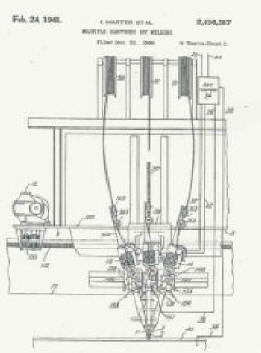
In a patent filed in 1944 by Harter ET Al, number
2,436,387, assigned to Babcock and Wilcox Company a 3
wire system was described. See photo at left of Figure 1 from their patent.
This broad based patent covers the use of various three phase power phasing to
control arc deflection and weld power distribution. A crude analysis of the arc
deflection caused by the interaction of the arcs is presented. They show the
benefits of using different phase angles, 60 versus 120 degrees. The
perspective of using an elongated arc verses just a higher current broader arc
is defined. Frankly it was not until the Multi-Cathode Gas Tungsten-Arc Welding
paper by Anderson and Yenni in 1965 that the reason for this benefit was
described (reference 5).
The Specification appears quite theoretical with no actual weld data or
parameters defined. However the theory of using a lower voltage on the
lead wire then progressively higher voltage on the middle and trial wires is
mentioned. Considering the period when this work was
published it is very advanced.
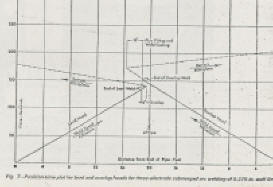
In a June 1952 Welding Journal article written by Clapp and Schreiner
entitled "Characteristics of Submerged Arc Welding with Three Phase Power," (reference 7) welding with three phase AC power is extensively reviewed.
The theory and benefits of various power phasing schemes is defined. They also
operated the system in inert gas to define the arc deflection phenomena
occurring. Plots are provided with various power phasing showing resulting arc
deflection. In addition to the theoretical analysis practical welding
parameters are provided for welding from ¼ inch (6mm) through 2 inch (50mm)
thick plate in two passes. The welding current for the second weld pass on 2
inch (50mm) plate for this two wire AC-AC system was given as 1740 amps lead,
1760 trail. Speed was 17.5 ipm (7.4 mm/s). Considering what the heat input is
for Electroslag welding, this is much lower! |
Don
Knight published a technical paper in the Welding Journal in April of 1954
entitled "Multiple Electrode Welding by the Unionmelt Process" (reference 8). He
reviews parallel wires, two wire AC-AC Scott as well as Series Arc for weld
surfacing. He presents specific applications and photographs of the
applications.
Kubli and Shrubsall presented a technical paper which was
published in The Welding Journal in November 1956 entitled, "Multipower
Submerged-Arc welding of Pressure Vessels and Pipe" (reference 8).They define the
various options for connecting to both DC and AC power. They describe the
benefits of using variable phasing AC to gain a forward deflecting trail arc to
control bead shape and eliminate undercutting. They present welding parameters
and show a number of applications in both pipe and vessel manufacture.
To increase welding speeds in the manufacture of gas and
oil transmission pipe extensive Laboratory work was done at the Linde Division
of UCC
Development Laboratory by among other Len Mauskaff in 1960 and 1961. Laboratory
results with the DC lead AC middle and AC trail system he developed were very
good. The system was installed at the US Steel pipe mill in Provo Utah.
Problems were encountered particularly at the finished end of the pipe,
particularly on the ID weld. Lack of weld penetration and narrowing of the weld
bead were observed. The results were inconsistent. Arc blow was felt to be the
problem with the DC arc causing backward arc deflection as the system came to
the end of the weld. Elaborate changes in the ID grounding were tried but did
not resolve the problems. The trail was terminated. In 1967 when making a
trial of an all AC system the weld data from the previous trial was reviewed
with Lou Warren the Welding Engineer (reference 9). |
With the
objective of developing a multiwre welding system that would be viable in
production myself (Jerry Uttrachi) and Joe Messina worked for several years at the
Linde Welding Labs
and defined an all AC system that achieved welding speeds higher than the
objective. This work was published in the Welding Journal June 1968
(reference 10). An extensive statistically design experiment yielded
unique power phasing and unexpected welding parameters to achieve excellent
results. The system was installed first at the U. S. Steel Pipe Mill
in Provo Utah.
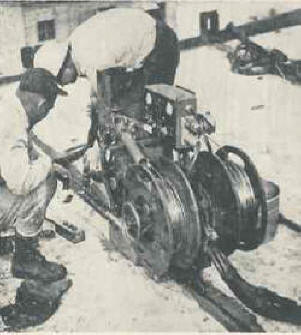
After extensive mill trials an finding none of the grounding or arc blow
problems previously experienced with the DC-AC-AC system, the mill manager,
Hank Huish, obtained funding to install
all new welding heads, controls and power for 5 ID and 4 OD welders (photo is of
OD welder). The results were so successful the American Bridge Division
of US Steel pipe mill in
Orange Texas also ran a mill trial and installed the three wire system on their
3 continuous OD Berkley cage welders and 4 boom ID welders. This was an
interesting trial since the mill had been equipped with DC-AC. We first
converted the mill to AC-AC Scott then added the third wire. On second and
third shift we shut down our third wire and left a reduced current Scott two
wire AC-AC system. On the 0.388 wall pipe we were welding we were able to
achieve speeds of 75 ipm (32 mm/sec) verses the maximum the mill had been able
to achieve with DC-AC of 60 ipm (25 mm/sec). This proved the benefit of the
forward arc deflection achieved with AC-AC. This three wire system was subsequently
installed in a number of foreign mills, including in Argentina, Italy, Kawasaki in
Japan and the British Steel pipe mill in the UK. Kaiser Engineering in Napa
also designed and built two pipe mills using this system, one for Iran and the
other for PMT in Mexico. They were excellent mills; unfortunately Kaiser did
not see fit to invest in their own mill in California which remained two wire
AC-AC Scott until it was recently closed. Stelco in Canada employed the
system on their new spiral mill designed to produce the Alaska oil and
natural gas pipe lines. The pipe used for what is referred to as the
Alaska Oil Pipeline was made in Japan and the natural gas line was never
built!
|
Perhaps
the most creative use of the three wire system was by the A.O. Smith/ Armco pipemill in Houston. They had a unique problem of having three massive
flash butt welders that they wanted to use as fixtures to make OD Submerged
Arc welds. However three OD welds would not meet the production output
requirements.
After extensive laboratory tests (reported in a Welding
Journal article entitled “Hot-Overlap Technique for Three-Electrode Submerged
Arc Welding of Line Pipe” reference 11) they successful obtained API approval
for a unique welding method. This was a very sophisticated
system for its time. Welds were made starting at both ends of the 40 foot pipe
and welding progressed to the center. At the center, one 3 wire welder
stopped and backed up and the other continued to weld through the still molten
flux from the first! All 11 welders (3 OD X 2 plus 5 ID) used our three
wire system. Each welding wire had volt and amp Esterline Angus strip record meters.
The control room with 66 strip recording meters was an impressive site!. Today that can easily be accomplished with a
computer but at the time, paper strip charts were used to troubleshoot potential problems
and assure the hot overlap was working properly.
In 1978 Uttrachi published a review of all of the multiwire
processes including parallel wires, DC-DC, DC-AC, AC-AC and three wire AC
(reference 12). It presents applications for each.
This review of multiwire-multipower history would not be
fair if it did not mention the extensive work done by others such as in Russia
and Japan. Both have published creative work quite prolifically. One paper in my
file is entitled Magneto-Hydrodynamic Phenomena During Twin-Arc Welding by Mandelberg, Sidorenko and
Lopata (reference 13) presents a good theoretical analysis of arc interactions.
I am most proud that one of their 10 references was our “Three Wire Paper;” the
only non Russian reference! An unusual occurrence.
|
|
SIDE BAR
DCCP POWER
A process patent, number 3,659,073, by myself and Messina
filed June, 1970 defines a method of Submerged Arc welding with DCCP power
(constant potential or voltage). Prior to that invention CP power was not used
for slow speed welds made at low current densities. The main reason for introducing it here is the oscillographs presented give some understanding of what is occurring under
the flux! A technical paper was also presented in the Welding Journal
(reference 14).
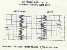
The oscillograph on the left labeled CC Power is a trace of
the amps and volts for a weld made with a 5/32 inch diameter electrode at 360
amps. That is 18,750 amps per square inch where published data at the time
said one could not use CP power below 40,000 amps per square inch. [For
perspective, an 0.045 GMAW weld made at 250 amps is 157,000 amps/square inch.]
Low current densities cause globular drop transfer. Assuming the drop diameter
averages the wire diameter that would yield about 5 drops per second.
These traces validate this calculation with the drop rate probably in the range of 6 to 10 per
second.
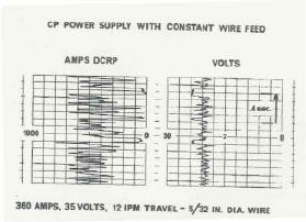
With conventional DCCP power the amperage trace shows large
excursions, ranging from almost 0 to 700-800 amp peak (see figure left).
In this trace, it appears the arc is actually extinguishing about 4 times in one
second. That is about the drop transfer frequency. What is occurring,
is as a molten drop leaves wire, the gap between the slowing feeding wire (30 ipm
wire feed speed) and the plate is larger than the available power supply
voltage! The wire must contact the plate or molten flux to have it reignite.
When it reignites it is probably starting on the hot puddle and leaning the arc
backwards. This creates a peaked undercut weld.

We found that by putting a very large inductor into the circuit, we were able to store enough
energy to deliver it back to the arc as the current tries to go to zero.
This keeps the arc alive and makes the process stable. Welds look like
those made with CC power, flat and uniform. From the traces made with
the system shown at left you'll note there are no arc outages. Note the voltage trace
shows peaks of 45 volts when only 40 open circuit voltage was available.
The extra 5 volts was delivered by the massive inductor.
The advantage of a CP system is in the control.
Maintaining the arc length with CC power requires a voltage control to maintain
the arc length. Prior to microprocessor controls this was not as accurate
or cost effective a means to achieve quality arc performance. To
perform the control function properly, low speed, low inertia motors and
appropriate controls were needed. Starting was also more difficult and
less reliable than achievable with CP power. Today many of these benefits
are less important since arc voltage controls can be made very accurate,
inexpensively.
|
|
TODAY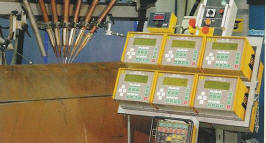
Today there are a number of 5 and 6 wire systems in use for
various applications. The use of microprocessor based controls makes these
systems viable for use. In addition there are numerous Submerged Arc flux
and wire products that are manufactured in all parts of the world. Weld
performance both physical and mechanical properties can meet the most stringent
needs for steel and some other materials.
|
|
General References:
- The History of Welding by R.D. Simonson, by
Monticello Books, Inc, Morton Grove, Ill, Printed April, 1969.
- “Pullman-Standard Active in Welding Developments”
The Welding Engineer, September 1937.
- “Welding Handbook,” American
Welding Society “1938 Edition
- “Welding in Tanker Construction,” by T. M.
Jackson; The Welding Journal October 1937.
- “Multi-Cathode Gas Tungsten-Arc Welding,”
by J. E. Anderson and D. M. Yenni The Welding Journal April 26, 1965.
- “Characteristics of Submerged Arc Welding with
Three Phase Power”, by E. A. Clapp and N. G. Schreiner; The Welding
Journal, June 1952
- “Multiple Electrode Welding by “Unionmelt”
Process,” by D. E. Knight published a technical paper in the Welding
Journal in April of 1954 entitled
- “Multipower Submerged-Arc Welding of Pressure
Vessels and Pipe,” by R. A. Kubli and H. I. Shrubsall, The welding
Journal, November 1956
- Welding with DC-AC-AC. Private Laboratory data
developed in 1960 and 1961 by Len Mauskaff and private Pipe Mill trial data
viewed at Geneva Steel Provo Utah with Welding Engineer, Louis Warren.
- “Three-Wire Submerged Arc Welding of Line Pipe,”
by Uttrachi and Messina Welding Journal, June 1968.
- “Hot-Overlap Technique for Three-Electrode
Submerged Arc Welding of Line Pipe,” by P.W. Ramsey, T. M. Even and G.
R. Wepfer, Welding Journal, October 1972.
- “Multiple Electrode Systems for Submerged Arc Welding,"
by G. D. Uttrachi, Welding Journal, May 1978.
- “Magneto-Hydrodynamic Phenomena During Twin-Arc
Welding,” by Mandelberg, Sidorenko and Lopata,
Avtomaticheskaya Svarka,
Number 2, 1969.
-
“A New DC Power System for Submerged Arc Welding,” by Gerald Uttrachi,
December 1970.
-
"Health of Arc Welders in Steel Ship
Construction," by US Surgeon General, 200 page review of WWII welders,
1947.
|
|
Page
1
2
3
4 (5
last)
Have a Welder?
Improve Weld Starts and Have Shielding Gas Cylinder Last at Least Twice as
Long!
Note: Our Patented
GSS
is Not Available in "Stores"
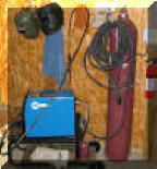
A home shop fabricator
in Georgia with a Miller TM 175 amp welder
purchased a 50 foot Gas Saver System ( GSSTM
) so he could use a larger cylinder
and mount it on the wall of his shop. He wrote:
"The system works great.
Thanks for the professional service and
a great product."
Click To See His Home Shop
A Professional
Street Rod Builder Had This to Say:
 With their standard MIG welder gas delivery hose the peak shielding flow at
weld start was measured at 150 CFH. That caused air to be sucked into the
gas stream causing poor weld starts. With the
GSS replacing their existing hose, the peak flow surge at the
weld start was about 50 CFH. Total gas use was cut in half. With their standard MIG welder gas delivery hose the peak shielding flow at
weld start was measured at 150 CFH. That caused air to be sucked into the
gas stream causing poor weld starts. With the
GSS replacing their existing hose, the peak flow surge at the
weld start was about 50 CFH. Total gas use was cut in half.
Kyle Bond, President, quickly saw the improvement achieved in weld start
quality as a significant advantage! Kyle, an excellent automotive painter,
was well aware of the effects of gas surge caused by pressure buildup in the
delivery hose when stopped. He has to deal with the visible effects in the
air hose lines on the spray gun in his paint booth! The paint surge is
visible and creates defects unless the gun is triggered off the part being
painted! We can’t do that with our MIG gun!

See Video Showing
What Users Say About Our Gas Saver System-CLICK Here or Picture

Check Out Welding
Math Site |
▲HOME
►CONSULTING
SERVICES
|