|
|
|
 HISTORY OF SUBMERGED ARC WELDING HISTORY OF SUBMERGED ARC WELDING
continued-- Page 2
JONES, KENNEDY, ROTERMUND PATENT
The key patent that defines the Submerged Arc process is US
Patent number 2,043,960 by Jones, Kennedy and Rothermund. This patent was
assigned to Linde Division of UCC and filed in October 1935. The
Specification states, Page 4, Column 2, Lines 4 through 7 that the application
was in part a continuation of applications Serial Numbers 657,836 and 705,893
filed in February 1933 and January 1934.
 There
are no other patents sited against or referenced in US Patent 2,043,960,
indicating this basic process and flux patent did not need to refer to that by
Robinoff. The Specification further discusses what is no doubt the Robinoff
“process” namely on Page 1, Column 2, Lines 23 through 59 parts of which are
quoted: “There is another known means of applying protective flux. It
consists in utilizing thick coating of finely divided material, a flux, which
covers the weld seam. The following is a typical analysis of such a flux…4.34%
Fe2O3…3% Fe. … Moreover the vigor of the arc submerged
under this flux projects a continuous cloud of material into the atmosphere. An
evidence of the amount of gas that is emitted by a flux…welders frequently wear
gas masks…it is not surprising gas holes should be found in the metal of the
weld.” There
are no other patents sited against or referenced in US Patent 2,043,960,
indicating this basic process and flux patent did not need to refer to that by
Robinoff. The Specification further discusses what is no doubt the Robinoff
“process” namely on Page 1, Column 2, Lines 23 through 59 parts of which are
quoted: “There is another known means of applying protective flux. It
consists in utilizing thick coating of finely divided material, a flux, which
covers the weld seam. The following is a typical analysis of such a flux…4.34%
Fe2O3…3% Fe. … Moreover the vigor of the arc submerged
under this flux projects a continuous cloud of material into the atmosphere. An
evidence of the amount of gas that is emitted by a flux…welders frequently wear
gas masks…it is not surprising gas holes should be found in the metal of the
weld.”
Quoting the main uniqueness of the process in the
Specification, Page 2, Column 1, Lines 20 through 37; “We have discovered a
novel process for electric welding wherein the necessary heat is generally by
the passage of a heavy electric current between the metal electrode (usually
bare) and the... objects to be welded…the current being carried across the gap
between the electrode and the objects by and through a conductive melt or
welding composition having appropriate electrical resistive properties. … The
welding composition serves as an active instrumentality, or welding media
inasmuch as it provides heating means, controls the rate of penetration and
quality of welding, purifies the molten metal and protects the molten metal.”
They also define a need for prefusing the flux
ingredients in the Specification, Page 2 Column 1, Lines 42 to 45; “The
chemical reactions between the components of the welding composition must be
completed before it is used in welding. Failure in this regard most surely
invites porosity.”
The patent further defines at least 4 compositions for
fluxes including a preferred method of manufacture.
One questionable fact however is their insistence that the process had no arc. In the Specification they even state a situation which
in their minds proved the point. Quoting Page 4, Column 1, Lines 42 to 53;
“Several circumstances show clearly that our process does not depend on the
formation of an arc of the usual type. If, while the weld is being made, the circuit
is opened externally of the weld and then closed again while the reactive
composition is still molten the current will immediately resume its flow without
any necessarily for moving the electrode into contact with the seam as it would
be necessary to reestablish the arc of the usual type. The heat for melting the
electrode is evidently developed in the conductive melt it self.”
See Side Bar Below
|
|
SIDE BAR:
IS THERE OR IS THERE
NOT AN ARC IN SUBMERGED ARC?
|
 The logic defined it the
Kennedy patent as related to there being "no arc" at first appears credible
until we understand just what is happening under the flux. Two
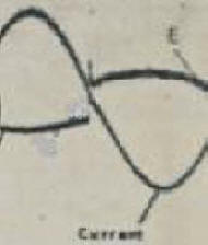
illustrations will show the presence of an arc. Referring to the
figure on the left. The oscilloscope trace on the left shows welding
voltage and current for a single wire AC weld made with Submerged Arc.
Note the sine wave for welding current since this power supply is of a sine
wave design. However note the arc voltage is essentially a
square wave. Also note that the voltage (labeled E) goes almost
instantaneously from a negative value to a positive value. In addition
you can see a voltage spike after the voltage goes positive.
This is a clear graphic
depiction of an arc. What is occurring is the voltage must be, at a
minimum, the sum of the anode and cathode voltage plus whatever resistance
exists across the arc gap itself. The arc does go out as the
current goes through zero. To reignite the arc, the voltage rises
until sufficient ions are produced and the anode and cathode voltages are
exceeded to start the arc again. The curved top of the square wave
exists because the resistive portion of the arc varies in voltage drop as
the current changes. If this were purely resistive melting the
voltage, as is the current, would be a sine wave.
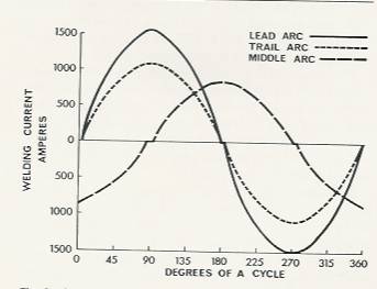
Since it is difficult to see the current holding at
zero for a brief period in that oscilloscope trace, a graphic made of three
wire welding system current traces is shown on the right. You can see
that for each of the three arcs as the current goes though zero it stays at
zero for a short time as the arc is reestablished.
|
|
 For modern Submerged Arc parameters
the amount of resistive heating in the molten flux is very low. It is
not an Electroslag process. However one should consider the typical wire
sizes and amperages quoted in the Kennedy patent, namely the smallest wire
being 3/16 inches with a current range of 500 to 800 amps. Also many
welds were made in heavy plate in one pass. The QA test we used for one
high current flux was made with 1/2 inch rod! Welding amperage was 2000
amps AC! The QA test lab had a hole in the ceiling which went into the
room above where a pipe was screwed to the floor to accept the 1/2 inch
diameter rod! For modern Submerged Arc parameters
the amount of resistive heating in the molten flux is very low. It is
not an Electroslag process. However one should consider the typical wire
sizes and amperages quoted in the Kennedy patent, namely the smallest wire
being 3/16 inches with a current range of 500 to 800 amps. Also many
welds were made in heavy plate in one pass. The QA test we used for one
high current flux was made with 1/2 inch rod! Welding amperage was 2000
amps AC! The QA test lab had a hole in the ceiling which went into the
room above where a pipe was screwed to the floor to accept the 1/2 inch
diameter rod! It is possible that at very slow
welding speeds with these low current densities with some of the fluxes
mentioned there could be a significant amount of resistance heating of the
molten flux. Therefore, explaining the postulate defined by Kennedy; the
arc reignites almost instantaneously since the molten flux is easily ionized.
Since the open circuit voltage, for properly designed power supplies, leads
the current by about 90 degrees, sufficient voltage is readily available to
have the arc start almost instantaneously. |
|
Page
 1
2
3
4
5(last) 1
2
3
4
5(last)
Have a Welder?
Improve Weld Starts and Have Shielding Gas Cylinder Last at Least Twice as
Long!
Note: Our Patented
GSS
is Not Available in "Stores"
A home shop fabricator
in Georgia with a Miller TM 175 amp welder
purchased a 50 foot Gas Saver System ( GSSTM
) so he could use a larger cylinder
and mount it on the wall of his shop. He wrote:
"The system works great.
Thanks for the professional service and
a great product."
Click To See His Home Shop
A Professional
Street Rod Builder Had This to Say:
 With their standard MIG welder gas delivery hose the peak shielding flow at
weld start was measured at 150 CFH. That caused air to be sucked into the
gas stream causing poor weld starts. With the
GSS replacing their existing hose, the peak flow surge at the
weld start was about 50 CFH. Total gas use was cut in half. With their standard MIG welder gas delivery hose the peak shielding flow at
weld start was measured at 150 CFH. That caused air to be sucked into the
gas stream causing poor weld starts. With the
GSS replacing their existing hose, the peak flow surge at the
weld start was about 50 CFH. Total gas use was cut in half.
Kyle Bond, President, quickly saw the improvement achieved in weld start
quality as a significant advantage! Kyle, an excellent automotive painter,
was well aware of the effects of gas surge caused by pressure buildup in the
delivery hose when stopped. He has to deal with the visible effects in the
air hose lines on the spray gun in his paint booth! The paint surge is
visible and creates defects unless the gun is triggered off the part being
painted! We can’t do that with our MIG gun!

See Video Showing
What Users Say About Our Gas Saver System-CLICK Here or Picture |
▲HOME
►CONSULTING
SERVICES
|