Second Reason for Gas Waste:
EXCESS FLOW SETTINGS
We have often found gas
flowmeters with the ball pinned to the top of the flow tube. Our tests show
this can be a 150 Cubic Feet per Hour (CFH) gas flow rate.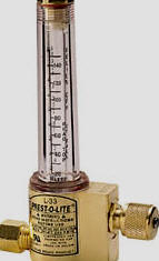
This excess is not only wasteful but causes poor weld quality.
The following is a quote from a
recent
article published in Practical Welding Today by Kevin Lyttle, Manager
Welding R&D for Praxair which states; “In many instances production site
surveys (of fabricators using MIG and Cored Wire) determine that shielding
gas flow rates typically are set in excess of 50 CFH. This can contribute
to poor weld quality as atmospheric gases are drawn into the arc zone
because of excess gas turbulence. Optimized flow enhances quality and
reduces shielding gas usage.” (Reference 3 Below)
Another article by The
Welding Institute in Cambridge England qualified the maximum flow rates in a
MIG gun before excess turbulence was created. For the most common
5/8 inch ID MIG gun nozzle, 48 CFH is the maximum flow rate before
turbulence is encountered. For those using low current MIG welders
employing the typical ½ inch ID MIG gun nozzle (used by most small shops
and home users) will allow only a 37 CFH maximum flow before encountering
turbulence. (Reference 4 Below)
Research performed to see
if increased flow could improve weld quality in a 5 MPH wind environment
yielded interesting results. This unpublished work showed that with a
standard 5/8 inch ID MIG gun nozzle, a 45 CFH shielding gas flow rate
produced less internal porosity than 65 CFH!
This
validates that turbulence created by the 65 CFH flow rate causes moisture
laden air to be sucked into the shielding gas stream and is counter
productive. Unfortunately many welders
and other folks involved in welding think "if some shielding
gas is good more must be better."
We find a number of people generally
knowledgeable about welding:
Don't understand the excess gas flow problem;
Don't understand that the high start gas surge
is a key reason for shielding gas waste and weld problems or if they
do;
Don't communicate the problem to welders;
Believe reducing system gas pressure helps,
not understanding that this approach creates more problems by eliminating
Automatic Flow Compensation
built into MIG gas delivery systems since the process was invented!
When discussing our
GSS with an engineer at a plant making highway trailers he said his gas
supplier just checked their flow rates and the 100 CFH set by flow control
orifices at their pipeline gas drops was fine!
Their gas supplier should have read the
article published by the Manager of Welding R&D for the largest shielding
gas producer, Praxair!
CLICK to see why he says in excess of 50 CFH GAS FLOW causes weld
quality problems!
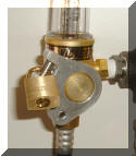
THE SOLUTION TO HIGH FLOW SETTINGS: If you’re
using flowmeters on cylinders or
on a pipeline
gas
supply a patented
lock (photo right) is available that allows the maximum flow rate to be set
and locked.
See Details.
The use of flowmeters on
pipeline gas supply has another significant excess flow problem.
If Gas Flow is Not Measured With a Portable
Flowmeter at the Gun Nozzle, Significant
Flow Variations from Pipeline Flowmeter Reading Can Occur. CLICK to SEE WHY


 A published
article quotes a Praxair representative indicating their fabricator
survey findings show
the average MIG welder consumes 6
times the shielding gas needed. Stated as a percentage,
83%
of the shielding gas used is wasted! (Reference
1 Below)
A published
article quotes a Praxair representative indicating their fabricator
survey findings show
the average MIG welder consumes 6
times the shielding gas needed. Stated as a percentage,
83%
of the shielding gas used is wasted! (Reference
1 Below)
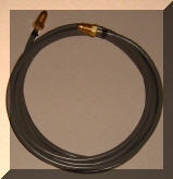
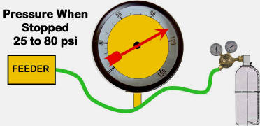 he
volume of gas extra in the gas delivery hose increases with pressure.
If the Absolute Pressure increases 5 times then the gas volume increases 5
times! We found that hose expansion creates another 13% increase in gas volume
he
volume of gas extra in the gas delivery hose increases with pressure.
If the Absolute Pressure increases 5 times then the gas volume increases 5
times! We found that hose expansion creates another 13% increase in gas volume

 THE
SOLUTION TO GAS SURGE:
THE
SOLUTION TO GAS SURGE: 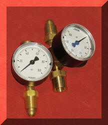 Check
Pipeline Pressure with our WAT PTD
Check
Pipeline Pressure with our WAT PTD