|
|
|
HISTORY OF MIG (GMAW) WELDING
continued-- Page 4
RECENT PROCESS ADVANCES
|
Several companies
have used modern microprocessors to analyze arc characteristics and develop
systems that make better starts, weld over gaps, allow CO2 to have reduced
spatter (particularly an issue in Japan and other countries where Argon prices
are much higher than in North America) and to make other MIG process advances.
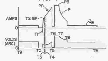
One of the more recent and well documented in the patent record is the Lincoln STTTM . Patent Number 5,001,326 by Stava
assigned to Lincoln was filed in February 1990. Other prior patents
are also sited. It describes a control system that allows control of weld
heat and the ability to achieve low spatter levels with CO2 shielding gas.
See above waveform from a figure in this patent. |
|
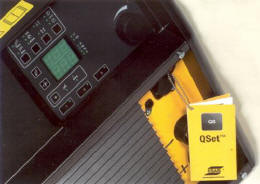 The
use of microprocessors allowed ESAB to recently introduce a MIG welder
called QSET.TM
A difficult
training task is instructing someone to set up Short Circuiting GMAW
(MIG "Short Arc.") ESAB introduced this product that
automatically sets the correct welding parameters for a given wire/gas
combination. The
use of microprocessors allowed ESAB to recently introduce a MIG welder
called QSET.TM
A difficult
training task is instructing someone to set up Short Circuiting GMAW
(MIG "Short Arc.") ESAB introduced this product that
automatically sets the correct welding parameters for a given wire/gas
combination.
The welding operator selects the wire feed
speed and welding machine sets the proper "short arc conditions. There
are no synergic lines, just a single knob to set the wire feed speed and
obtain the optimum welding parameters. The welder can still elect to modify
arc length by means of a voltage trim control. A further benefit of
system is that the control algorithms maintain a constant power in the arc
and depth of penetration, even if the contact tip distance changes. Because
the arc stability is closely controlled, there is also less weld spatter
and, therefore, less post-weld cleaning.
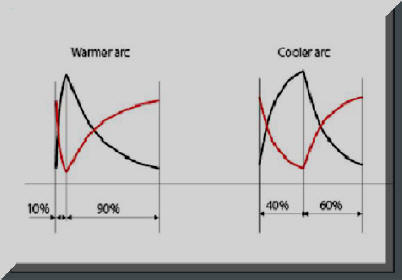 ESAB
explains that in a stable "Short Arc" process the ratio of short circuit and
arc time lies in a narrow range. The QSET welder continually measures
and controls the short circuit pattern. A test weld is made and in a
few seconds the welding machine optimizes and maintains the optimum
conditions. Maintaining the proper "Short Arc" conditions is important
to avoid cold welds or "cold lap" as it is often referred. ESAB
explains that in a stable "Short Arc" process the ratio of short circuit and
arc time lies in a narrow range. The QSET welder continually measures
and controls the short circuit pattern. A test weld is made and in a
few seconds the welding machine optimizes and maintains the optimum
conditions. Maintaining the proper "Short Arc" conditions is important
to avoid cold welds or "cold lap" as it is often referred. |
|
 Another
recent advance if the use of Tandem MIG. Although versions of this process
were patented as early as 1957, little was done with the process until recently.
Modern controls and power allow process variations that make these processes
viable. Another
recent advance if the use of Tandem MIG. Although versions of this process
were patented as early as 1957, little was done with the process until recently.
Modern controls and power allow process variations that make these processes
viable.
The use of multiple Tandem MIG systems for making circumferential welds in
line pipe is very productive.
|
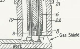
| Shielding
Gas Delivery Optimized
The early developers of MIG welding understood what was needed to properly
deliver shielding gas such as the need for pressures on the inlet side of
the gas solenoid
 being above
25 psi. This was needed to have the gas flow remain at the
preset level when spatter built-up in the torch nozzle and the torch cable
bent and twisted in operation. However this created excess shielding
gas stored in the delivery hose when welding stopped that was mostly wasted
at the weld start. being above
25 psi. This was needed to have the gas flow remain at the
preset level when spatter built-up in the torch nozzle and the torch cable
bent and twisted in operation. However this created excess shielding
gas stored in the delivery hose when welding stopped that was mostly wasted
at the weld start.
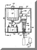
Stauffer in 1982 patented a
device ( patent figure left, Patent Number 4,341,237) to reduce this start
surge. He also understood that some extra gas was needed at the
start to quickly purge the torch nozzle weld start area or air. He
built an accumulator into his system that delivered the proper amount of
extra start gas. However his device used low pressure eliminating the
automatic flow compensating feature and since the pressure was low the
accumulator and therefore the device was quite large and comp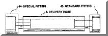 lex. lex.
A much similar and effective
system (patent figure right) was developed that optimized the gas flow at
the weld start. It also eliminates the excess stored gas
significantly reducing gas waste. It still delivers a sufficient
amount of gas at the weld start, at a flow rate that avoids excess
turbulence, to purge air from the MIG gun nozzle and weld start area. It was patented by Uttrachi in 2003,
Patent Number 6,610,957 (Hey that's me!) Uttrachi
had additional patents for other devices to reduce gas waste and improve
weld start quality issued in 2006, Patent Numbers 7,015,412 and 7,019,248.
|
|
There are many innovations we have no doubt missed.
However by referencing the patents mentioned one can find substantially more
patents and references that may be of interest. Patents have the objective
of teaching the reasons why something works. A patent as a bargain between
the Government and the inventor. The Government offers a short-term monopoly in
return for a full description of the invention, which is published
by the Patent Office. This exchange of a monopoly for a full description
underpins the patent system and leads to published patent documents
being the most comprehensive source of technical information in the world, for
practically every area of technology. That is why one obtains a limited
time monopoly so
the information is fully disclosed for posterity. Some inventors do a
better job than others of fully disclosing their insight into the product or
process details. |
|
REFERENCES
The references below give the student of MIG some base to search
further so as not to have to reinvent the wheel, or worse conduct future
research without knowing it was already invented!
-
"Controlling the Melting Rate and Metal Transfer in
Gas-Shielded Metal-Arc Welding. Part II," by Al Lesnewich, Welding
Journal 1958, 37(9), pp 418-s
-
"GMAW-A Versatile Process on the Move," by Kevin
Lytte, Welding Journal, March 1983, pp15.
Some Other References Not Sited But
Significant
-
"Controlling the Melting Rate and Metal Transfer in
Gas-Shielded Metal-Arc Welding. Part I," by Al Lesnewich, Welding
Journal 1958, 37(8), pp 343-s
-
"Characteristics of Inert Gas Shielded Metal Arcs,"
by Muller, Greene, and Rothschild, Welding Journal August 1952, pp 717-s
- “Energy Distribution in
Electric Welding,” by C. E. Jackson and A. E. Shrubsall, Welding Journal, 29 (10) Research Supplement 520-a
to 521a (1959).
- “Control of Penetration
and Melting Ratio with Welding Technique,” by C. E. Jackson and A. E. Shrubsall, The Welding Journal, 32
(4) Research Supplement 172-s to 178-s (1953).
-
"The Effect of I2RHeating on Electrode
Melting Rate," by Wilson, Claussen and Jackson, Welding Journal, 1956,
35(1), pp 1-s
-
"The Inert Gas Shielded Metal Arc Welding Process"
by Wooding, Welding Journal, 1953, 32(4,5); pp299-s, 407-s
-
"The Aicromatic Welding Process'"
by Muller.
Gibson, and Roper, Welding journal, 1950 29(6), pp 459-s
-
"Inert Gas Shielded Welding Arc Behavior and Metal
Transfer Characteristics" by George Skinner and Yenni, Electric Arc
and Resistance Welding, IV July 1954, American Institute of Electrical
Engineers, Publication S-64, pp 16-27
-
"Arc and Bead Characteristics of the Aluminum Self
Adjusting Arc," by Needham and Smith, 1958 British Welding Journal, 5,
pp 66-76
-
"Carbon-Dioxide Shielded Consumable Electrode Arc
Welding" by Rothschild, Welding Journal 1956, 35(1) pp 19-29
-
"GMAW Shielding Gas Flow
Control Systems" by G. D. Uttrachi,
Welding Journal 2007, 86 (4) pp 22-23
|
| Page 1
2
3
(4 last)
Have a Welder?
Improve Weld Starts and Have Shielding Gas Cylinder Last at Least Twice as
Long!
Note: Our Patented
GSS
is Not Available in "Stores"
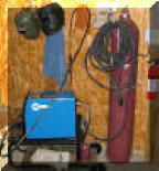
A home shop fabricator
in Georgia with a Miller TM 175 amp welder
purchased a 50 foot Gas Saver System ( GSSTM
) so he could use a larger cylinder
and mount it on the wall of his shop. He wrote:
"The system works great.
Thanks for the professional service and
a great product."
Click To See His Home Shop
A Professional
Street Rod Builder Had This to Say:
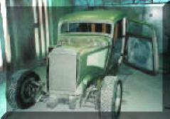 With their standard MIG welder gas delivery hose the peak shielding flow at
weld start was measured at 150 CFH. That caused air to be sucked into the
gas stream causing poor weld starts. With the
GSS replacing their existing hose, the peak flow surge at the
weld start was about 50 CFH. Total gas use was cut in half. With their standard MIG welder gas delivery hose the peak shielding flow at
weld start was measured at 150 CFH. That caused air to be sucked into the
gas stream causing poor weld starts. With the
GSS replacing their existing hose, the peak flow surge at the
weld start was about 50 CFH. Total gas use was cut in half.
Kyle Bond, President, quickly saw the improvement achieved in weld start
quality as a significant advantage! Kyle, an excellent automotive painter,
was well aware of the effects of gas surge caused by pressure buildup in the
delivery hose when stopped. He has to deal with the visible effects in the
air hose lines on the spray gun in his paint booth! The paint surge is
visible and creates defects unless the gun is triggered off the part being
painted! We can’t do that with our MIG gun!
GAS SAVER SYSTEM (GSS TM)
PURCHASE INFORMATION

Check Out Welding
Math Site
|
|
"WARNING:
"Weld
Safely" |
 |
►CONSULTING
SERVICES
|