|
Friction Stir
Welding (FSW)
History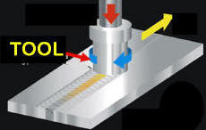
In 1991 a novel welding method was conceived.
The process was named Friction Stir Welding (FSW) by the inventors at The
Welding Institute (TWI.) TWI is one of the worlds leading independent
research and technology organization and is based in Cambridge, England.
A US patent for FSW, # 5,460,317, was filed in November
1992 with W. H. Thomas et al as inventors, assigned to TWI. A
number of companies around the world are using the process in production,
primarily for joining aluminum. |
|
The Process
FSW
employs a rotating cylindrical "tool" rubbing against a butted
joint between to pieces to be joined. Friction between the "tool" and
the material heats the joint to a temperature where it becomes soft and
plastic but well below the melting point. The "tool" is then
pushed along the joint line. The parts have to be securely clamped in a manner that prevents the
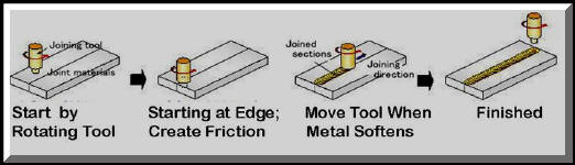 abutting
joint faces from being forced apart. The softened material in front of the
"tool" is pulled or dragged to the trailing edge. It
leaves a solid phase bond between the two pieces. For many
aluminum alloys the fact that the material is not melted may allow very high
weld strength compared to low joint efficiency with arc welding. The above
picture is a schematic of the process sequence. abutting
joint faces from being forced apart. The softened material in front of the
"tool" is pulled or dragged to the trailing edge. It
leaves a solid phase bond between the two pieces. For many
aluminum alloys the fact that the material is not melted may allow very high
weld strength compared to low joint efficiency with arc welding. The above
picture is a schematic of the process sequence. |
There is not much heat
involved outside the actual joining area . An interesting
anecdote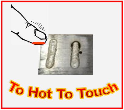 involves my first observation of the process in operation. It
was at an ESSEN Welding Fair in Germany. Five or six foot long pieces
of ~3/8 inch thick aluminum were being butt welded. Typical of my
observation of allowed unsafe practices in Europe (compared to the US,) there were no guards or ropes
around the FSW machine! Show visitors were standing very close, shoulder
to shoulder
along the length of the weldment. As the rotating welding "tool"
passed in front of them, one person touched the welded plates about 18 inches
after the "tool" had passed. Then one by one, others next to him touched
the plate, getting closer and closer to the rotating "tool." Finally one
touched about 6 inches behind the slow moving "tool" and quickly pulled back
like a child contacting a hot stove! involves my first observation of the process in operation. It
was at an ESSEN Welding Fair in Germany. Five or six foot long pieces
of ~3/8 inch thick aluminum were being butt welded. Typical of my
observation of allowed unsafe practices in Europe (compared to the US,) there were no guards or ropes
around the FSW machine! Show visitors were standing very close, shoulder
to shoulder
along the length of the weldment. As the rotating welding "tool"
passed in front of them, one person touched the welded plates about 18 inches
after the "tool" had passed. Then one by one, others next to him touched
the plate, getting closer and closer to the rotating "tool." Finally one
touched about 6 inches behind the slow moving "tool" and quickly pulled back
like a child contacting a hot stove! |
|
TWI holds a number of patents related to
FSW. Anyone using the process
needs permission (a license) from TWI. It is TWI's policy to grant
non-exclusive licenses to any potential users on reasonable commercial
terms. (Note: A former colleague and good friend Dr. Robert John retired
as the CEO of TWI in July 2010. Bob was CEO for 6 years and was
previously the Institutes business
manger. He developed the license arrangements which allowed TWI to generate
and expend the monies needed to advance the science of the process-which
they did and continue to do.) |
| Friction Stir
Welding Applications Although FSW is being developed and
has been used to some extent for a variety of base materials; it's success
to-date has been joining aluminum.
Marine Construction The shipbuilding industry was one of the first to adopt the process. FSW is useful for decks, sides bulkheads and floor panels; for aluminum
extrusions; helicopter landing platforms; masts and booms. |
ESAB
FSW
in Sweden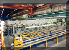
ESAB’s trade name for
FSW is
SuperStir.™ This machine is installed at Sapa in Sweden. It is used to make
large panels in welded lengths of up to 45 feet for ships etc. The machine
has three welding heads, which allows welding from two sides of the panel at
the same time. The heads can be positioned on the same side of the panel and
starting at the center of the workpiece weld in opposite directions from
each other. |
|
ESAB FSW in
Norway
This ESAB SuperStir™ is installed
at Marine Aluminum Aanen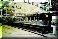 seen
& Co. It is used mainly for manufacturing panels for ships and
railcars. Maximum panel size 50 x 20 feet. Aluminum alloys ranging in
thickness from 1/16 to 5/8 inches are weldable in one pass. The plant
incorporates automatic material handling systems to keep high operating
rates. The welding operation is fully automatic and all parameters are
computerized with an easy to use Man Machine Interface. Production started
in the autumn of 1996 and has produced over 500,000 feet of weld. seen
& Co. It is used mainly for manufacturing panels for ships and
railcars. Maximum panel size 50 x 20 feet. Aluminum alloys ranging in
thickness from 1/16 to 5/8 inches are weldable in one pass. The plant
incorporates automatic material handling systems to keep high operating
rates. The welding operation is fully automatic and all parameters are
computerized with an easy to use Man Machine Interface. Production started
in the autumn of 1996 and has produced over 500,000 feet of weld. |
|
Aerospace Industry
NASA
partnered with Lockheed Martin and MT Aerospace to manufacture the first
full-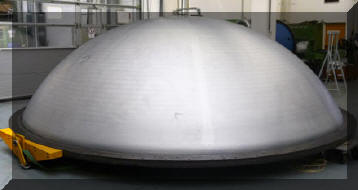 scale FSW spun-formed tank dome for liquid propellant tanks. The 18 foot
diameter tank dome is made from high strength 2195 aluminum-lithium alloy. FSW allows the use of thinner, high strength alloy reducing weight by 25%
compared to current designs. To achieve the size needed a blank was
constructed by FSW two commercial off-the-shelf plates reducing cost of raw
material. scale FSW spun-formed tank dome for liquid propellant tanks. The 18 foot
diameter tank dome is made from high strength 2195 aluminum-lithium alloy. FSW allows the use of thinner, high strength alloy reducing weight by 25%
compared to current designs. To achieve the size needed a blank was
constructed by FSW two commercial off-the-shelf plates reducing cost of raw
material. |
|
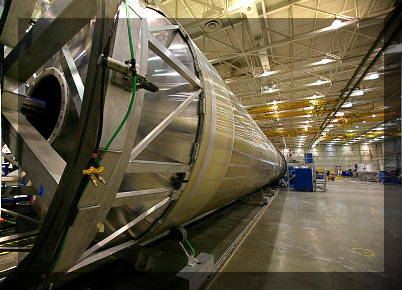 Longitudinal
and circumferential
FSW
are used for rocket booster tanks.
FSW is used
to make the Space Shuttle external tank that contains the liquid hydrogen
fuel and liquid oxygen oxidizer. Prior to using FSW the
7000 series aluminum alloy achieved only 50% joint efficiency with arc
welding. The material had to be made twice as thick and the bulk machined
away leaving a tapered section twice the thickness in the weld joint area.
This created a lot of material waste, excessive time and cost. Longitudinal
and circumferential
FSW
are used for rocket booster tanks.
FSW is used
to make the Space Shuttle external tank that contains the liquid hydrogen
fuel and liquid oxygen oxidizer. Prior to using FSW the
7000 series aluminum alloy achieved only 50% joint efficiency with arc
welding. The material had to be made twice as thick and the bulk machined
away leaving a tapered section twice the thickness in the weld joint area.
This created a lot of material waste, excessive time and cost.
|
Note: FSW can appear deceptively simple - it is NOT! My group was
involved in the support of the system sold to make the Space Shuttle tanks;
one of the first large systems installed in the USA. The actual welding
 process
and simple “tools” (at the time) were not that complicated; the massive and
powerful holding fixture was! The parts must be prevented from moving as
welding progresses. This requires very high forces and that large system
cost over 5 million dollars! In addition, since the mid 1990’s when
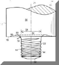
that particular system was installed, the “tools” have become more complex. The newest designs can make
quality appearance top and bottom deposits. Some have a
shape which assists moving the softened material from in front of the "tool" to
the rear. (The sketch right is of a
"tool" from a recent patent. The working part called the nib is screw
shaped enhancing movement of the softened material around tool and the upper area
helps form the top surface of the deposit.) process
and simple “tools” (at the time) were not that complicated; the massive and
powerful holding fixture was! The parts must be prevented from moving as
welding progresses. This requires very high forces and that large system
cost over 5 million dollars! In addition, since the mid 1990’s when
that particular system was installed, the “tools” have become more complex. The newest designs can make
quality appearance top and bottom deposits. Some have a
shape which assists moving the softened material from in front of the "tool" to
the rear. (The sketch right is of a
"tool" from a recent patent. The working part called the nib is screw
shaped enhancing movement of the softened material around tool and the upper area
helps form the top surface of the deposit.) |
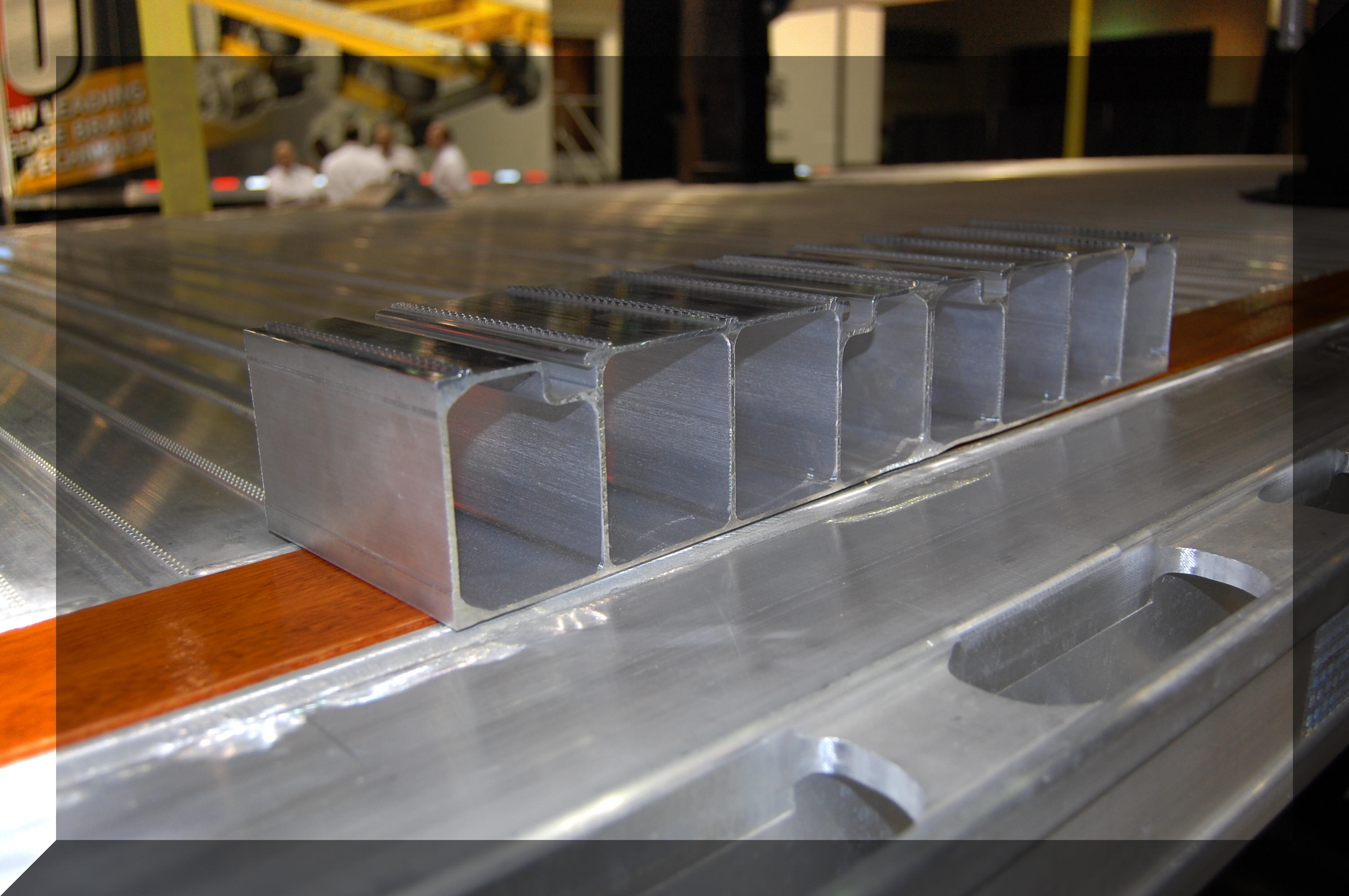 Transportation
Industry Transportation
Industry
Fontain
Trailer introduced
FSW for flatbed trailer manufacture. Market demand for
lighter, stronger trailers to haul more payload was a key reason for a new
design. In addition, lighter weight was needed to compensate for
tractors that are getting heavier due to the additional emission control
technology. Fontain reports the typical 48-foot flatbed weighs about 10,000
pounds and requires 1,400 screws, 44 steel I-beams, eight wing braces, plus
wood and aluminum strips for the flooring – a total of 3,700 parts.
By employing
FSW techniques they reduced the weight of this all aluminum
trailer to 8,000 pounds.
FSW
is also used for welding light weight high speed trains, tank cars etc |
More information on the History of:
-
Submerged Arc
Welding (SAW)
-
MIG Welding (GMAW)
-
Electroslag Welding (ESW)
-
TIG Welding (GTAW)
can be found
at these links on our site (just click on the process).
|
|
 Stop
Wasting Shielding Gas!! Stop
Wasting Shielding Gas!!
See YouTube Videos
Including Our Patented MIG Shielding
"Gas
Saver System" (GSS)
Science of MIG
Shielding Gas Flow Control
Why MIG Gas Waste
Detailed Review of GSS
Short Overview of GSS-90 Seconds
What User Say About
GSS
Welding Race Cars
Rat Rods-Then and Now
Welding: Go Green
|
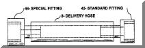
New innovations are still occurring in the welding industry. Our
recent inventions optimize MIG shielding gas flow at the weld start (2003
Patent Number 6,610,957; figure left and 2006 Patent Numbers 7,015,412 and 7,019,248) These devices reduce excess stored gas by over 80%
when welding stops. This significantly reduces gas waste that published
data shows typically exceeds over
60% of what is used! Reducing shielding gas waste can save a
MIG user over 50% of gas use while improving weld start quality. Our
Patent 7,462,709 issued in 2008 and defines a device that allows most
flowmeters to be locked at the desired settings avoiding excess wasted gas.
Reducing waste
is very important in a competitive world environment.
|
|
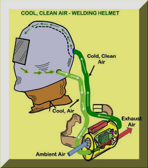 In
2012 we were granted two patents related to helping a welders environment.
These welding helmet designs not only filter the air entering the helmet
they also cool the air using a Thermoelectric Cooling Module. Cooling
the head helps cool the whole body. Excessive heat is a common complaint of
welders. This helmet helps solve the excess heat problem by
providing cooled filtered, breathable air. In
2012 we were granted two patents related to helping a welders environment.
These welding helmet designs not only filter the air entering the helmet
they also cool the air using a Thermoelectric Cooling Module. Cooling
the head helps cool the whole body. Excessive heat is a common complaint of
welders. This helmet helps solve the excess heat problem by
providing cooled filtered, breathable air.
We are searching
for a company to license these designs, including fabricators that
employ a number of welders who would benefit from the reduced heat and
better environment. Contact
Jerry_Uttrachi@NetWelding.com if interested. |
Have a MIG Welder?
Improve Weld Start Quality and
Have Shielding Gas Cylinder Last at Twice as Long!
Note: Our Patented
GSS is Not Available in "Stores"
We Focus on Saving NOT
Selling Shielding Gas"
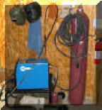
A home shop fabricator
in Georgia with a Miller TM 175 amp welder
purchased a 50 foot Gas Saver System (
GSS
TM
) so he could use a larger cylinder
and mount it on the wall of his shop. He wrote:
"The system works great.
Thanks for the professional service and
a great product."
Click To See His Home Shop
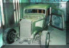
A Professional
Street Rod Builder Had This to Say:
With their standard MIG welder gas delivery hose the peak shielding flow at
weld start was measured at 150 CFH. That caused air
to be sucked into the gas stream causing poor weld starts. With the replacing their existing
hose, the peak flow surge at the weld start was about 50 CFH. Total gas use
was cut in half.
Kyle Bond, President, quickly saw the improvement
achieved in weld start quality as a significant advantage! Kyle, an
excellent automotive painter, was well aware of the effects of gas surge
caused by pressure buildup in the delivery hose when stopped. He has to
deal with the visible effects in the air hose lines on the spray gun in his
paint booth! The paint surge is visible and creates defects unless the gun
is triggered off the part being painted! We can’t do that with our MIG gun!
GAS SAVER SYSTEM (GSS TM)
PURCHASE INFORMATION
|