 The
photo top of page, shows two of the few weld samples kept over the years because of
their uniqueness. The Submerged Arc weld cross section, upper photo
right side, was made with a 3/4 inch root gap, very low angle sidewall
(<12 degrees) and
utilized a two pass per layer split bead technique. This was the
typical joint used for making 12 inch thick reactor vessels for nuclear
power plants. This joint and split bead technique were used by
US manufacturers of main reactor vessels, namely, Combustion Engineering,
B&W and CB&I. They used AC-AC power connected employing a 90 degree
phase shift called the Scott connection. This provided a controlled
arc deflection and assisted achieving consistent side wall edge wetting.
The use of all AC power avoided arc blow.
The
photo top of page, shows two of the few weld samples kept over the years because of
their uniqueness. The Submerged Arc weld cross section, upper photo
right side, was made with a 3/4 inch root gap, very low angle sidewall
(<12 degrees) and
utilized a two pass per layer split bead technique. This was the
typical joint used for making 12 inch thick reactor vessels for nuclear
power plants. This joint and split bead technique were used by
US manufacturers of main reactor vessels, namely, Combustion Engineering,
B&W and CB&I. They used AC-AC power connected employing a 90 degree
phase shift called the Scott connection. This provided a controlled
arc deflection and assisted achieving consistent side wall edge wetting.
The use of all AC power avoided arc blow.
As we had done with the manufacture of gas and oil transmission pipe my
associate and I developed a three electrode, all AC power system to increase
welding speeds and metal deposition rate over the two wire (electrode) AC-AC
systems these vessel manufacturers were using. Note, during this time
our company (now owned by ESAB) sold specially designed
fused fluxes to both the line pipe and nuclear vessel industries and had
essentially 100% of the flux and wire business. We provided the welding technical
support to both of these high technology industries. The concept of using all AC power was
developed over many years in the 'late '50s and early 60's and several technical papers were published on the
subject in the AWS Welding Journal.
Refer to the this web page on the
History of Submerged Arc welding and the references sited.
Our three wire, all AC power system
used the same power configuration we developed and that was being employed
successfully by many pipemills in the US, Canada, Mexico, the UK, Japan and
several other countries. Weld metal deposition rate was up to 75 lbs/hr with
total welding current exceeding 3000 amps. The power was all AC with
arc deflection controlled with the proper phasing of one arc to the other.
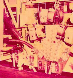
The photo upper right is a commercial installation of the three wire all AC power
system in production.
Some believe that a DC lead will
provide significantly more
penetration than AC power. However in a deep groove arc blow can effect penetration
and side wall fusion when DC is used limiting maximum current levels.
A penetration equation developed by
Clarence Jackson after making hundreds of welds defined that weld
penetration was proportional to Amps4.
AC power does have less penetration than DCRP when making simple
bead-on-plate deposits. However using Jackson's
equation we can show a 5% increase in AC current compensates for the decrease
and provides an arc much less susceptibility to arc blow.
A report available for purchase on Multiwire
Submerged Arc welding systems covers from 2 to 4 wire systems and includes this
current and penetration analysis.
Sub
Arc Narrow Gap Summary:
We
worked with one of the major nuclear vessel producers in a field test of
this all AC power, three electrode system. Longitudinal test welds were
successful. What were the problems encountered? Why was it not successful
at the time for the key circumferential weld joints
where the increased speed was most important? A confidential report
can be prepared to discuss the system, and these issues.
 With
today's technology these shortcomings can be overcome.
Email
for a quote.
RECENT
CONFIDENTIAL REPORT PREPARED:
A
report was recently prepared for a client with
these "relatively narrow gap procedures" for welding 11 inch thick
HY-80. The resulting weld joint required 75% less welding materials
than conventional procedures with much less distortion. This
approach also produced crack free deposits without stress relive heat
treatment. A past experience welding 12 inch thick HY-100 was also
used to provide these recommended procedures, welding flux/wire
recommendations, expected weld properties and special welding nozzle design.
MIG NARROW GAP
WELDING:
The weld section, left in the picture
on the top of this page, is
even more unique. This cross section is from a MIG weld made in 2 inch thick plate
with a 1/2 inch gap and straight sidewalls. These are some
details:
 *
The weld beads were placed one
above the other.
* Weld deposition
rate was 25 lbs/hr!
* How was that
deposition rate achieved with solid wire?
* How was uniform
side wall wetting achieved?
All those
answers and more are available in a Confidential Report, available for a fee.