| Holley Double Pumper in Car 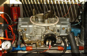
See Video
" Tuning Holley Carb"
|
Once it was realized, by using an
Air/fuel meter, the problems with the Vacuum
Secondary Carb could be quantified, the solutions became obvious. One
confusion was the method given in several references on how to adjust
the Jet Size and Power Valve fuel passage size. It was indicated if
the Jet size is reduced significantly the Power Valve fuel passages could be
drilled out to compensate. |
| It was advised to increase the diameter to
equal the area lost with the Jet size reduction. However this did not
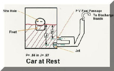
work and provided an excessively rich mixture. Looking at the geometry
of the system it is obvious the Power Valve fuel passages are
significantly higher in the fuel bowl (See distance P in the schematic of
rear fuel bowl "Car at Rest" below) and therefore would not flow as much
fuel for a given size as the Jets (J in schematic). Rather it would
be more proportional to the fuel head ratio (distance from fuel level to
gas passage) as well as the area. This comes much closer to what
should be done and what resulted in the optimum settings. |
| Calculate Jet Size to Compensate for Blocked Power
Valve The deviation caused by the physically higher Power Valve fuel passage is
most dramatic when calculating the needed Jet size increase when the Power Valve
is blocked on the Secondary. If one used the methods proposed in the most
references, for the 850 Double Pumper the calculations would be:
-
The original Power Valve fuel passages were .067 inches. Since there
are two power valve passages and two jets we will calculate on the basis of
one pair. The area for a .067 inch passage is .0035 square inches.
-
The number 80 Jets which came on the Carb are .093 inch diameter or .0068
square inches
-
The total area would be .0068 + .0035 or .0103 square inches
-
This equates to a diameter of .114 inches which is a # 94 or 95 Jet
(tables available in references provided).
On the other hand, to compensate for the differences in fuel head in the
secondary float chamber you modify the Power Valve area by the ratio of
the fuel head heights. Namely 0.97 inches (J in above schematic) from the fuel level to the center line
of the Jet passage versus .56 inches (P in above schematic) from the fuel level to the centerline of
the Power Valve fuel passage. Or .56/.97 = .58 or :
-
The Power Valve effective area would be .0035, as above, times .58 or .002
square inches
-
Adding this to the .0068 inches as noted above gives a total effective
area of .0088 square inches which calculates to a diameter for the new Jet of
.108 inches. This is a Jet size of # 88 versus the previous calculation
of # 94 to 95. It fact this is the one which worked!
|
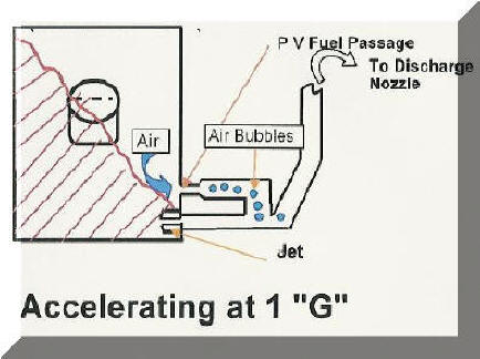 |
Fuel Level When Accelerating
The schematic above depicts the fuel level when the car
accelerates at 1"G". Effectively it is like the car being tilted up at a
45 degree angle with a 1"G" force acting downward on the fuel due to gravity and
another 1 "G" rearward due to acceleration. Note the higher Power Valve
fuel passages would be exposed to air not fuel.
|
| In fact the jets themselves are at risk of
being exposed to the air. (That's one reason Pro Stock Drag cars mount
the carbs sideways!) To correct this problem two steps are taken.
First the Power Valve Fuel Passages are blocked with a plug (see photo far
left below) .
Want to measure the variations in fuel
level? Check out this new device. |
 |
 |
 |
 |
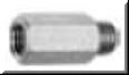
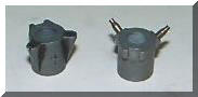
| Second the jets (larger ones to compensate for the blocked power valve
passages) are moved with an extension (see above center left photo) that places them
in the rear of the bowl where they can not be uncovered even with 2 "G's" or
greater acceleration. Jet extensions require a special "notched float"
(photo center right) to provide the proper clearance. You can purchase
these two items as a set. Since we're on the subject of rear bowl modifications,
the photo to the far right above is an internal Bowl Vent Extension (also called
a 'Whistle") that
prevents fuel pushing forward into the vent which exits at the top on the bowl
into the carburetor when abruptly stopping. This can cause flooding.
It should be added as well. |
|
Accelerator Pump
Even with the proper jets, a lean bog would occur when the Secondary butterflies
were instantly opened when
accelerating. The normal fuel delivery system could not provide enough
fuel in time. The accelerator pump circuit
supplies added fuel to match the increased air flow that occurs instantly.
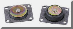
It was found that a 50 cc front pump improved the response over the 30 cc pump
which came with the carburetor (see the larger 50 cc versus 30 cc pump diaphragm
on left photo below). Optimizing the Squirter size and Cam took trial and error (right in
photo below). When installing the larger "Squirters" use a higher capacity
"Squirter Screw" (photo far right below). A Yellow Cam is used on the Primary and a Brown Cam (quick
fuel shot but does not completely empty the accelerator pump reservoir) on the
Secondary. A Holley Representative I talked with at the Rockingham Drag
Racing track was a help with suggestions as well.
|
 |
 |
 |
| These modifications solve the problems of acceleration and deceleration. In a
light Street Rod, blocking the Power Valve and using larger Secondary Jets has little effect on fuel mileage since the
Secondary
with their progressive linkage are
seldom brought into play when cursing or in any normal driving. However
when needed there is all the power desired, immediately! |
|
 A
subtle but important tuning item are the accelerator pump cams. With
the 50CC pumps I found the brown cam was best for the rear bowl. It
gives a quick shot of fuel but does not empty all the fuel in the reservoir. A
subtle but important tuning item are the accelerator pump cams. With
the 50CC pumps I found the brown cam was best for the rear bowl. It
gives a quick shot of fuel but does not empty all the fuel in the reservoir.
Used a yellow cam
pump for the front bowl. They come as a set for under $25.
You'll need some trial and tests to get the proper ones for the car weight,
axle ratio, tire grip and acceleration achieved.
This is what
Holley says about them: "Holley accelerator pump cams will allow you to
"tailor" accelerator pump performance to the engine's actual requirements.
They include cams that have a different shape or profile to give different
results. Cam "lift" directly affects the accelerator pump stroke, and,
therefore, pump capacity. Ramp profile or shape controls the "timing" of the
shot. A steeply-rising ramp shape will give a fast, heavy fuel shot right
off idle. Conversely, a gently sloping ramp will spread the pump action over
a longer period of time." |
|
Other Modifications
A few other modifications are worth mentioning. An
electric choke kit was added to the Double Pumper which comes with a manual
choke. A choke is needed to assist starting and the electric one works
fine with no need for a cable. One caution. With the two 50 cc pumps
DO NOT put your foot to the floor when starting or you'll be changing wet plugs!
A 1/4 depression of the accelerator peddle is all that is needed!
(Leaving a car show late last year when it was cool at night, I mistakenly gave
it almost 1 full pump!! It missed all 10 miles home! Next morning I pulled
the plugs and sure enough one had obviously not fired. Simply cleaned them
and all was fine. Even after starting for this years "season" and
carefully depressing only 1/4 throttle, it started fine!)
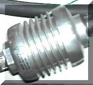
The Double Pumper does not come with bronze fuel filters.
I thought since I use a K&N stainless filter (left photo below) before the blue
Holley high capacity electric fuel pump and another in line after the pressure
reducing regulator that would be OK. I found that I occasionally got some
flooding when decelerating after a quick hard run. Again the Holley folks
thought it might be a high fuel level ( which after checking it was not) or
dumping fuel into the Carb from the bowl vent so I added higher vent tubes but
the problem remained. They then thought it was a sticky fuel pressure
regulator. Since I had another I swapped it with no improvement (pressure
set at 7 psi).
This problem had not existed with the Vacuum
Secondary Carb,
|
 |
 |
I deduced one difference was the lack of bronze fuel filters (right photo above) in
the Double Pumper Carb. These do create a small pressure drop and help avoid an
instant rush of fuel past the large fuel inlet needle valves after the bowls are low on a rapid acceleration "Banzai Run". I
installed them and that has solved the problem! The car has been running
fine for over three years without one instance of flooding (accept as mentioned
above when I used "I Know Better" procedure! |
An
interesting article in the July 2005 issue of "Hot Rod" Magazine describes a
new product that provides an explanation for the filter working!
Check it out! |