|
Tip of the Month

Low Pressure Devices Vs Gas Saver System!

A Shielding Gas Saving Article Published in
a Prominent Technical Journal is FOOLISH! |
Low Pressure Flow Controls & Orifices Mounted at Wire Feeders Don't Work
Although several products claim to reduce shielding gas waste, some can actually “increase not decrease” total gas use and are often rejected by welders! Perhaps a "Gas Saleperson" promting these products is aware they increase not decrease gas use LOL! The worst offender was promoted in an article in a prominent welding journal; prompting writing this Tip of the Month. A number of managers and welders report the poor performance of the product, which they removed. One removed 70 another discarded 50 after seeing the problems. (Details in PDF Report see below link.) The results from tests of that product versus a conventional quality flow control show it's problems.
 This
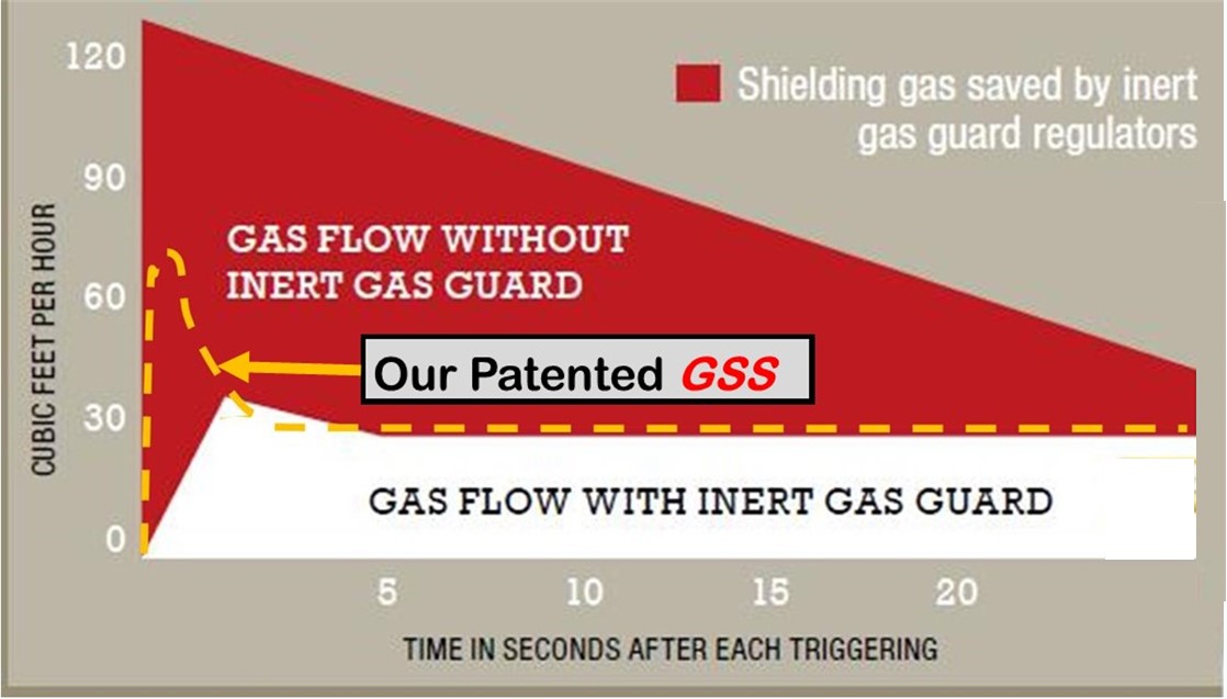
graph from the published article shows the performance of the product referred to, the Harris 301-RF low pressure flow control. It shows it does not have sufficient extra gas at the weld start to purge air. It's just like starting in air for a few seconds creating excess spatter and possibly internal porosity. This
graph from the published article shows the performance of the product referred to, the Harris 301-RF low pressure flow control. It shows it does not have sufficient extra gas at the weld start to purge air. It's just like starting in air for a few seconds creating excess spatter and possibly internal porosity.
We put the Yellow line on the graph showing that our simple, lower cost, patented Gas Saver System (GSS) provides the needed extra start gas and better weld starts.
|
It's Even Worse! Low Pressure Eliminates Automatic Flow Compensation.
BUT a worse feature, is it eliminates Automatic Flow Compensation. The engineers who designed the quality MIG and TIG flow controls when these processes were introduced in the 1950s knew this feature was critical. That’s why ALL ESAB/Victor, ITW/MILLER/Smith and other quality shielding gas flow control devices use a minimum of 25 psi- NOT foolish low pressure!
Heck, even the cheap regulator flow controls from China use ~50 psi! In discussions with Chinese engineers at the huge Beijing Welding Exhibition, all clearly understood “automatic flow compensation.” The following discusses the issue and MIG/TIG shielding gas flow in detail! |
A TEST Documents The Problem:
The following table provides test results with a conventional flow control device that operates at 25 psi and a commercial low-pressure Harris Gas Guard 301-RF  system (right) subjected to varying restrictions. Both were initially set to flow 31 CFH as noted in Blue. The controls were left at the initial settings as if they were padlocked. MIG gun restrictions were then added and removed (as if the gas ports were alternately clogged and cleaned) to vary the amount of restrictions. Resulting flow rates, measured at the MIG Gun nozzle exit using a portable flowmeter, are shown in the table below. system (right) subjected to varying restrictions. Both were initially set to flow 31 CFH as noted in Blue. The controls were left at the initial settings as if they were padlocked. MIG gun restrictions were then added and removed (as if the gas ports were alternately clogged and cleaned) to vary the amount of restrictions. Resulting flow rates, measured at the MIG Gun nozzle exit using a portable flowmeter, are shown in the table below.
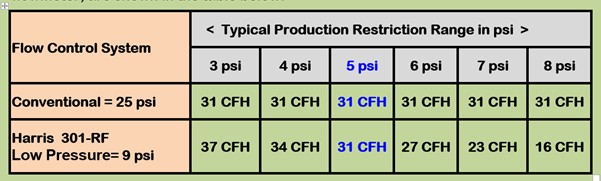
Note the flow with the conventional regulator/flowmeter stayed consistant at 31 CFH. The flow with the low pressure Harris 301-RF varied from a high of 37 CFH to a low of 16 CFH! Outside of acceptable flow control range in a qualified welding procedure!
In addition the flow calibrated pressure gauge included with the Harris Model 301 is only reading the 9 psi pressure so it did not change! It read about 31 CFH for all the flows in the tests!
This gives the false impression that the flows remained constant. You can be out of the flow range defined in your Welding Procedure Qualification and not know it! If gas is blocked from flowing it will still read the preset value of 31 CFH!
MANY MORE DETAILS, FABRICATOR TESTIMONIALS WHERE THE HARRIS LOW PRESSURE DEVICES WERE REMOVED AND DISCARDED ARE PRESNTED IN A DETAILED REPORT. CLICK Here Or JESTER HAT TO DOWNLOAD A PDF  |
|
 Purchase
Training Purchase
Training
Products
Purchase Gas Saver System
|
What do you think of the Tip Of the Month?
Received this positive feedback regarding a Tip of the Month discussing
the effects of leaks in a gas delivery system:
"I have been in Metal Manufacturing for over 25 years. Recently I have been assigned to a department manufacturing centrifugal compressor impellers where a cover is TIG and MIG welded to the top of blades. Your Tip of the Month is the first plausible explanation (for occasional defects) I have come across that can explain this phenomenon and why it may be more prevalent in the springtime and in high humidity periods." |