Tip of Month Achieve
Don't Use A Flow Rate That Creates Turbulence!
Who would use more than these flow levels? The answer is often every MIG welder at the weld start! The reason and way to fix it, is covered in this TIP of the MONTH! In addition, some folks when setting shielding gas flow believe, "If some is good, more must be better" - They Are Wrong! |
|
Tip of the Month
Calculations of MIG Shielding Gas Use Are Bogus! They are often low by over 80% ! |
|
A Patented Gas Delivery Hose System that:
|
| Patented FB3 and FB4 GSS’s are for smaller shops and home welders. "Cuts" gas waste while improving gas "Shield." They assist as skills devlope to make quality, good looking welds or maybe to become a "master welder!"These welders use smaller size gas cylinders and often make shorter welds and tack welds. The “gas blast” at every weld start not only wastes considerable gas, it leads to excess spatter, poor weld shape, and possibly internal porosity. That excess flow rate pulls air into the shielding gas stream. The turbulent flow created lasts for a short time even after flow rate reduces until desired laminar flow is attained. This inferior gas shield exists for much of a short weld! Peak flow rates can exceed 150 CFH. By saving wasted shielding gas at the weld start, higher gas flows can be used when welding in drafts or outdoors. This provides better weld quality while still using less total gas! |
Testimonials Al Hackethal sent this email after purchasing a 3 foot, FB3 GSS for his small MIG welder. “Well, I can't believe it. I never thought a hose could make that much of a difference. The weld quality (with the GSS), and even penetration is considerable better. Almost no spatter! Initially thought that my imagination had kicked in, but then realized that the gas I'm buying is actually working the way it's supposed to. Glad I found your website. This is one of the few things that really works better than any info could suggest. I understood the theory, though in practice I understood it much better after the first couple of welds. Now I have better looking welds and almost no spatter, which means less grinding and finish work! In addition, the tip was cleaner after the job I just did. Another customer, Jason Insley, had this to say “Everything worked fine. And my weld starts have definitely improved since installing the GSS |
In Summary
|
“Cut Gas Waste - Improve Gas Shield” CLICK to Download PDF of SilverShield GSS Flyer in 2 Column Formate CLICK to Download PDF of SilverShield GSS Flyer in 1 Column Formate |
|
The success of the Lincoln Electric Company is due to the business methods developed by J. F. Lincoln. He evolved and sustained unique business practices that allowed Lincoln Electric to be a major factor in the development of the welding industry. He managed the Company from 1914 until his death in 1965 at age 82. Bill Irrgang succeeded Jim Lincoln and continued his business philosophies until 1986. The company adapted to current times and continues to be very successful as a worldwide, focused welding business. A summary of the key points of the business management books written by J. F. Lincoln and some direct experiences related to the company is available as a PDF download. The similarities to the management techniques employed by Henry Ford as well as Fred Taylor's work on scientific management are included.
|
|
Many of his thoughts are applicable to today�s environment! �For the first time in American history, free enterprise is being destroyed by high-minded incompetents who have only the best interest of American at heart, but whose knowledge of what makes the economy successfully progress is completely nil.� �Because of this and their soft-hearted �do-gooder� attitude in which they are perhaps entirely honest, they are destroying America.� �Desire for freedom was why America was founded.� �Our present policy of government-promised security is providing a race of incompetent softies� �The program of the various deals, �New� and �Fair� has already stopped and reversed the development on which we depend for our future progress and national security.� �We have developed a philosophy which shuns individual responsibility.� �When all citizens depend on government support, it takes most of the earnings of most producers to provide a bare living for all.� �One way to remedy a slip (in the economy) is to borrow from the future and live at the old rate on borrowed money.� �The problem with the next generation suffering for our sins leaves us cold. Why worry about them they are not even born yet.� �The loafer should not be allowed to live on the efforts of the worker.� �This is an easy way out but its national suicide, as history shows.� �Every nation that has disappeared has gone through the same sequence and the same result; 1st softening of peoples ambition and lessening incentives; 2nd increase in numbers of people who fail to develop themselves or their latent abilities; 3rd a feeling of helplessness; 4th public support for all who ask for it; 5th insolvency of the economy as fewer will work to care for the careless and because of the softening process; and 6th being surpassed by a virile nation that has not gone soft.� �Few (politicians) understand what makes free enterprise succeed.� �Will the average person exercise their responsibility as a citizen of a representative government so the freedom on which is future depends will continue? Our experience under Roosevelt and Truman answers the question with a definite NO.� � Putting the power of the state over the operations of industry is called socialism by some, communism by others; in actuality, it is called a totalitarian government where the citizen is a serf of government directed by bureaucracy. �No bureaucrat can operate any industry successfully.� �If the present attitude in Washington continues this will not be a place where either you or I or your grandchildren can live with any degree of satisfaction.� In 1938 Jim Lincoln retaliated and refused to invest in the USA and visited Australia where they were rugged individuals. Lincoln worked with a local steel company who promised to supply the companies product needs. The Lincoln Electric Company (Australia) Proprietary Limited opened the same year of his visit. Jim Lincoln also started a business in the England in the 1930�s. However, at the end of WWII he strongly disapproved of the elected Labor Government and sold the business, including the Lincoln name in the UK, for $400,000! |
|
Totalitarianism-My Experience My experience with the effects of totalitarian rule reinforces the illogic of a central bureaucracy managing the needs and wants of the individual. In the mid 1970�s we participated in a technical exchange with a famous Russian welding institute. We both had targeted objectives, ours was electroslag welding and fused flux manufacture, and theirs bonded flux manufacture and flux cored wire. After several years, we made little progress. We decided to keep the last meeting small. Two representatives from Russia came to the Ohio R&D lab that I managed, a researcher who we had grown to know and the �interpreter� (who participated in every exchange visit and was actually more than an interpreter!) We had been told that in a previous visit to our Ohio Lab they believed we had taken them to the �mayor�s� house for dinner, as they could not believe it was the home of our business manager. I decided for this last visit to pick them up at the airport and take them to McDonalds for lunch to show how the average American ate. During lunch, the researcher asked an interesting question. What was the difference in pay between our engineers and technicians? I thought about the salaries, the overtime pay the technician earned and the increased taxes paid by the engineer because of his salary level and felt it was about 30%. I then asked what the differences were in Russia. He said, �Much more and difficult to measure. For example, because of my position I can get an apartment my technician cannot, he and his family live with his parents. I can get a new car, it may take 6 months to a year but I can get on the list, he cannot. Food is inexpensive for both but for many other products my family gets priority.� I then asked about the cost of a refrigerator to get a feel for a typical product price. He said, �Oh refrigerators are very cheap because the central planners made many more than people need! However, you cannot get a washing machine because they did not plan enough!� That prompted a conversation in Russian between him and the �interpreter� which was obviously contentious! During that same visit, I had to ask my good friend and Cubin born technician to stay home because of his expressed passionate dislike of Russians. His father had a small farm in Cuba and my friend would help pick tobacco from their field and roll a cigar for his dad. He and some of his family were able to leave Cuba when the Castro regime took over but his dad stayed. His farm was taken away from him by the regime but it did not go to the �people� it went to the communist mayor of the town! My friend�s emotions were so high, it was better to have him stay home then perform a demonstration for our guests as had been planned! (Some years later, he was able to get his dad out of Cuba during the �Freedom Flotilla.�)
A
reinforcement of the effects of central planning occurred in the mid 1980�s
when we had
|
| Karl Marx: I recall a biography of Karl Marx I read some years ago. A writer visited his apartment and said he had to sit in a chair that had dried puss from boils! Marx and his family lived in squalor! Found the following in the Internet: �He was covered with carbuncles, furuncles and boils and he complained about them in letters. They were painful, and large, and at times a doctor had to lance and drain them. In describing one such operation, he said the size of the boil was as big as his wife's fist. Marx wrote he was covered head to toe in the eruptions. He also wrote about having them on his backside and his most private parts. Doctors, long after his death, determined he was suffering from Hidradenitis Suppurativa, a disease of the sweat glands found in the armpits and groin.� When reading his writings, I wonder how many folks consider how this may have influenced or distorted his perspective! |
|
Some social safety net programs are needed and can be provided by private charities or the federal government. However an incident reminds me of the abuses and unintended lifestyle consequences that are created with federal programs rather than local operated programs or private charities. I obtained two masters degrees in the evenings, while working in a welding R&D lab. I would eat on the run between work and class. The primary "dinner" spot was a hot dog push-cart operated by an immigrate from a former iron Curtain country. I recall we would discuss his desire to expand his business and I suggested buying another cart and hiring an employee. He was reluctant to trust anyone to be as hard working as he was or to assure they were honest! He was having to address some of the risks all entrepreneurs must face! One evening, a friend of his was ordering a hot dog and discussing his personal dilemma. He was complaining that he had two children, a boy and a girl, but his "federal government housing" only allowed him two bedrooms. The children were getting old enough that they needed separate bedrooms. The hot dog vendor told his friend, "Well, if you have one more child you'll be eligible for three bedrooms!" His solution was based on the rules some "bureaucratic do-gooder" thought were reasonable! But like having more children without being married allows more government subsidies, this creates inappropriate, destructive behavior. If the federal government feels obligated to get involved in these programs, give the monies to state and local governments where these unintended consequences and irrationalities can be monitored and funds better applied. |
|
Some Thoughts for Today: It is currently much easier to start businesses around the world than it was when Jim Lincoln objected to government polices and sought to develop businesses outside the US. Companies and individuals can leave an oppressive situation and move offshore.
There
certainly are some inequities in the economy that should be fixed.
Tax loopholes are fostered by
Lobbyists, Lawyers, Accountants and
Politicians who exploit them to
support their jobs! These should be closed. True entrepreneurs
who risk their money should be rewarded with no limit. However
rewarding Wall Street types with huge, unlimited bonuses when they have none
of their own money at risk is irrational. The same applies to
corporate executives when huge unlimited bonuses can be earned with no
personal financial risk. This often promotes very short-term thinking and
possible manipulation of financial results.
For public companies, assuring
the appropriateness of top executive salaries
is the role of the Board of Directors employing compensation committees
and proper salary surveys. Stockholders should insist these tasks be
appropriately structured, which is current law. For a vast majority of companies,
executive salaries and bonuses
are appropriate and are
being properly scrutinized. The
Board of Directors must be held Revise the tax code, be it a multilevel flat tax or whatever-but make it simple.
Fabricators: The following is a way to save shielding gas waste and significant cost so you can be more competitive and hire more folks! |
|
To evaluate a high waste case, assume gas waste is the high side defined in the literature, i.e. gas usage is 6 times what is needed with a high duty cycle which reduces Labor Percentage. Shielding gas would now be 32% of welding costs! Probably higher than actual unless your welders are also setting much to high a flow rate. |
 NO
Gas Waste Case:
Most MIG gas use calculations make no consideration for
shielding gas waste. The resulting weld cost pie chart
is shown on the left. This is what is typically published as a way
of calculating shielding gas costs.
Shielding gas is
shown as only 5 % of total cost and less than wire costs which are 7%.
This is based on an unrealistic assumption of no
gas waste.
It�s Bogus! NO
Gas Waste Case:
Most MIG gas use calculations make no consideration for
shielding gas waste. The resulting weld cost pie chart
is shown on the left. This is what is typically published as a way
of calculating shielding gas costs.
Shielding gas is
shown as only 5 % of total cost and less than wire costs which are 7%.
This is based on an unrealistic assumption of no
gas waste.
It�s Bogus!
|
|
Don�t feel badly if you find out your using far more gas than you should! An analysis done for a major fabricator showed they were wasting 83% of their Argon and 90% of their CO2! In addition to the high gas surge at the weld start they were setting excess flow rates and they also had leaks.
Want information on how to
measure and monitor leaks on an ongoing bases?
CLICK TO SEE our Lean Welding
Manufacturing Self Study Programs related to gas us
Click on Email ICON and ask for more information.
|
| MIG Shielding Gas Flow Control is Much More Complex Then it Appears |
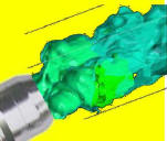 1700's, Daniel Bernoulli, would "Roll Over in His Grave" because of our
lack of understand of MIG shielding gas control and the cause of very
high gas waste! 1700's, Daniel Bernoulli, would "Roll Over in His Grave" because of our
lack of understand of MIG shielding gas control and the cause of very
high gas waste!
MIG gas flow control is much more complex than it first appears. We’ll provide a quick overview and link to other pages in this website for more details if you want to understand it fully. |
Who would use more than these flow levels? The answer is, often every MIG welder at the weld start! The reason is covered below! In addition, some folks believe, "if some is good, more must be better" when it comes to shielding gas flow-they are wrong! |
|
An important factor is the pressure needed in the gas delivery hose to flow gas through a welding machine (or wire feeder,) MIG gun cable, gun and nozzle will vary from about 3 to 7 psi. The amount needed will change as flow restrictions change when welding. These flow restriction changes are caused by: a) bends of the small gas passage in the gun
cable, |
 With
these flow restriction changes the flow rate set with a flowmeter needle valve or
an orifice in a regulator/flowgauge would cause
the flow to vary significantly. The engineers who designed the MIG flow control
system when the process was introduced, knew this was a problem and employed a
flow control approach that would automatically compensate for restrictions downstream of
the flow control device. The approach used relies on the fact
that the speed of the a gas through a small opening in a needle valve or
orifice cannot exceed the speed of sound! When the speed of sound is
reached, that speed in a
small opening is what controls flow and it does not depend on the downstream
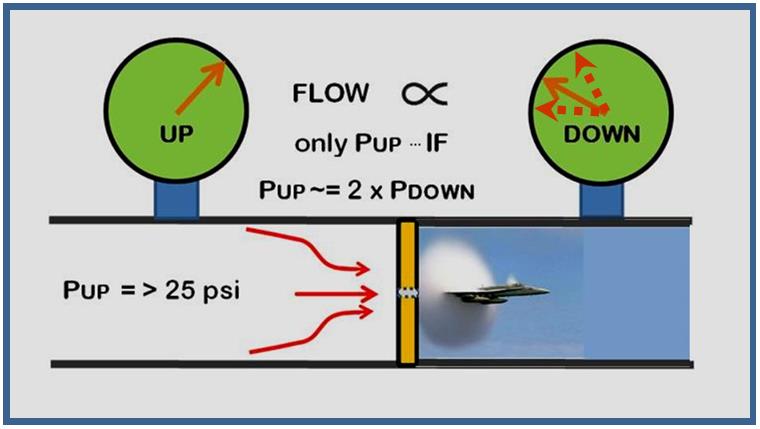
pressure. To achieve what is called "choked flow" that provides
this Automatic Flow Compensation, the absolute pressure (gauge pressure + atmospheric pressure) upstream
of the flow control device must be 2.1 times the absolute downstream
pressure. Using 2:1 for an approximate calculation, see figure below
for the pressure required: With
these flow restriction changes the flow rate set with a flowmeter needle valve or
an orifice in a regulator/flowgauge would cause
the flow to vary significantly. The engineers who designed the MIG flow control
system when the process was introduced, knew this was a problem and employed a
flow control approach that would automatically compensate for restrictions downstream of
the flow control device. The approach used relies on the fact
that the speed of the a gas through a small opening in a needle valve or
orifice cannot exceed the speed of sound! When the speed of sound is
reached, that speed in a
small opening is what controls flow and it does not depend on the downstream
pressure. To achieve what is called "choked flow" that provides
this Automatic Flow Compensation, the absolute pressure (gauge pressure + atmospheric pressure) upstream
of the flow control device must be 2.1 times the absolute downstream
pressure. Using 2:1 for an approximate calculation, see figure below
for the pressure required: |
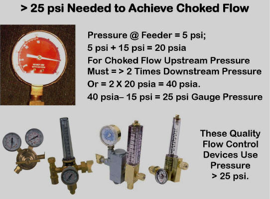
The figure left shows the pressure needed to achieve "choked flow" is 25 psi. It is no coincidence that quality flow controls shown in this picture use pressures from 25 to 80 psi. The engineers that designed MIG and TIG flow control systems when these processes were introduced, knew of the varying flow restrictions and designed to automatically compensate so flows remained at the initial settings. |
If high pressure solves the consistent flow problem, is there
a downside? Yes, when welding stops and the solenoid closes in the
welder or wire feeder, gas continues to flow though the needle valve or
orifice and quickly fills the gas delivery hose with more gas which raises the pressure.
It reaches the pressure of the regulator or pipeline. This
stores a lot of excess gas equal to, in the case right (80+15)/(4+15) = 5
times the hose volume of excess gas. We also find a typical 1/4 inch ID
hose expands another 13% at the high pressure. Therefore, the excess gas in the
hose is 5 x 1.13 = 5.7 the physical hose volume!
However using pressure less than 25 psi, as some have tried with devices
like "Gas Guards" creates bigger, less obvious problems than what they are trying
to solve! This eliminates Automatic Flow Compensation causing wide variations in flow. See test result comparisons of a proper flow control
with a commercial low pressure device.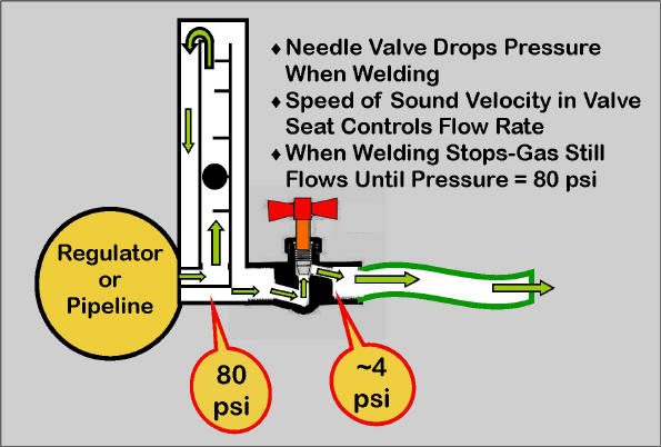 |
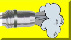 That excess gas, stored in the gas delivery hose when welding stops, "blasts out"
of the MIG nozzle at each weld start! This high flow not only wastes gas but the
high velocity (we have measured peak flows exceeding 200 CFH) creates a high
degree of turbulence that causes air to
be pulled into the shielding gas stream. The air causes problems with
weld quality and produces excess spatter. This gas waste can be over
half the total gas used. That excess gas, stored in the gas delivery hose when welding stops, "blasts out"
of the MIG nozzle at each weld start! This high flow not only wastes gas but the
high velocity (we have measured peak flows exceeding 200 CFH) creates a high
degree of turbulence that causes air to
be pulled into the shielding gas stream. The air causes problems with
weld quality and produces excess spatter. This gas waste can be over
half the total gas used.
The solution to the gas waste and high peak gas surge is our patented Gas Saver System. It is a simple, custom extruded, small ID, heavy wall gas delivery hose with a peak flow limiting orifice built into in the welder/feeder end brass fitting. It maintains system pressure and therefore Automatic Flow Compensation. The controlled small amount of extra gas it retains, quickly purges air from the weld start zone and MIG gun nozzle. Purging air from the weld start area and gun nozzle is essential for quality weld starts. Some devices have been tried over the years that attempt to control flow at the wire feeder or welder to eliminate surge and have been rejected by welders! We used to agree with management believing welders just didn't care about "saving gas." Since forming WA Technology and working with a number of welders in production operations related to gas flow control we have found they were right! These devices such as Simple Orifices, Flowmeters or Regulators with Orifice Control that are mount at the wire feeder do not provide the needed extra start gas. Stauffer in a 1982 patented device discussed the issue and added a reservoir to hold and deliver some extra start gas! When encountering flow control at the wire feeder welders either drill out the orifice or if a flowmeter or regulator mounted at the wire feeder is being used they increase the steady state flow in attempt to compensate! They may not even know they are trying to provide some extra purge gas but they see the inferior weld start result and attempt to compensate for the lack of purge gas! Increasing the steady state flow DOES NOT fully solve the lack of some extra start gas and it WASTES RATHER THAN SAVES GAS! IT DEFEATS WHAT THE MANAGEMENT WAS ATTEMPTING IN THE FIRST PLACE! CLICK TO SEE DOCUMENTED CASES OF THE PROBLEMS WITH LACK OF START GAS CLICK TO SEE WHY WE SELL DIRECTLY ON THE INTERNET AND NOT IN "STORES'" The patented Gas Saver System : Note, the peak flow control orifice does not control the steady state flow while welding - that is set by the existing conventional gas flow control device. For cylinder gas supply that can be a regulator/flowmeter or a regulator/flowgauge. On pipeline supply it can be a flowmeter or simple orifice located at the pipeline drop. It will prevent setting very high excessive flow rates if that is an issue. |
| You can Google these names to see their contribution to the understanding
of gas flow. They may not have used the words "choked flow" but all
would understand what it accomplished and why it would be needed in MIG
welding flow controls!
Galileo Galile 1563-1642 Was one of the
early contributors to understanding sound
1700-1782 Pioneer in fluid mechanics. We use his work to define how airplanes fly!
Robert Boyle 1627-1691
Herman Helmholtz 1821-1894
Ernest Mach 1838-1916
Osborne Reynolds 1842-1912
|
Don't Tolerate Gas Leaks! Leaks work 24/7 and also allow moisture laden air to enter the gas pipeline.
|
|||||||||||||||||||||||||||
|
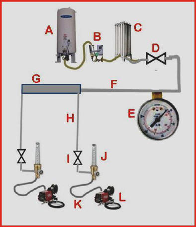
Schematic- Pipeline Gas Supply A= Liquid Tank B= Economizer C= Evaporator D= Shut-off Valve E= Pressure Gauge F= Pipeline G= Header H= Pipeline Drops I= OSHA Required Valves J= Flowmeter K=Gas Delivery Hose (Preferable our Gas Saver System) L= MIG Feeder
|
|||||||||||||||||||||||||||
| Evaluating fabricators gas usage, some are wasting considerably more shielding gas than the apparently accepted 3 to 5 times what they could use! Many accept that they have pipeline and hose leaks. However few have quantified how much gas these leaks are causing! | |||||||||||||||||||||||||||
|
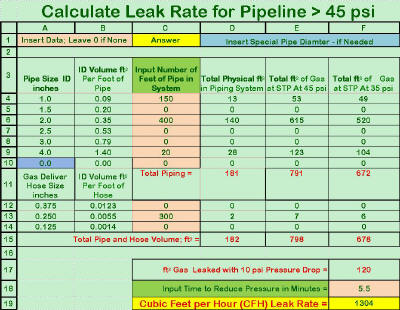
Pipeline Leaks:
It is a Leak Down test used very effectively in regulator manufacture. The method can be quickly used as an ongoing check for leaks.
|
|||||||||||||||||||||||||||
| Our "Lean Welding Manufacturing-Shielding Gas" Learning Program defines this Leak Measurement approach as well as many other gas cost related issues. It is a 70 + page document and includes an Excel Spreadsheet that helps make measuring gas leaks relatively easy. | |||||||||||||||||||||||||||
|
It also provides the following:
CLICK TO SEE PROGRAM DETAILS AND HOW TO PURCHASE
|
|||||||||||||||||||||||||||
|
Cryogenic Tanks: We receive a number of
inquiries
Liquid Argon is stored at about -300 deg F. The storage tanks use several methods to insulate the very cold liquid. They have an evaporation rate from about 1/2 %/day of their full rated volume (for modern new tanks) to 2 %/day or more for older tanks. Therefore a 3,000 gallon tank (325,000 CF @ atmospheric pressure and temperature, STP) when not flowing gas will evaporate 6500 CF/day with a 2% evaporation rate and only 1600 CF/day with a 1/2 % evaporation rate. Some newer higher
efficiency tanks also incorporate Bottom Line: Disconnecting a pipeline from the gas supply over a weekend requires significant purging on start-up to remove the moisture laden air that flowed back through the leaks. The use of a modern cryogenic tank and fixing leaks is the proper solution! |
|||||||||||||||||||||||||||
|
Calculations of MIG Shielding Gas Use Are Bogus!
They are often low by over 80% ! |
|||||||||||||||||||||||||||
|
First, evaluating the simplistic approach typically published: General Assumptions:
|
|||||||||||||||||||||||||||
|
NO Gas Waste Case: With the above assumptions and no consideration for shielding gas waste, the resulting weld cost pie chart is shown on the left. This is what is typically published as the method of calculating shielding gas costs. It�s Bogus! |
|||||||||||||||||||||||||||
|
Shielding gas is shown as only 5 % of total cost and less than wire costs which are 7%. This is based on an unrealistic assumption of no gas waste.
|
|||||||||||||||||||||||||||
|
High Waste Case: To evaluate a high waste case, assume gas waste is the high side defined in the literature, i.e. gas usage is 6 times what is needed with a high duty cycle which reduces Labor Percentage |
|||||||||||||||||||||||||||
|
Shielding gas would now be 32% of welding costs! Probably higher than actual unless your welders are also setting much to high a flow rate.
|
|||||||||||||||||||||||||||
|
Where Does the Extra Gas Come From and Go? Each time welding stops a significant amount of excess gas fills the delivery hose from gas source to feeder. This excess is expelled at high velocity at every weld start. An example of a fabricator who tested our Gas Saver System (GSSTM) provides a graphic picture of how much gas is wasted at the weld start.
CLICK to SEE many more production examples at: |
|||||||||||||||||||||||||||
|
Another reason for gas waste is welders often believe �If some is good more must be better,� when it comes to setting gas flow rates. With typical flowmeters we have measured 150 CFH flow at the MIG Gun nozzle when the needle valve was fully opened. The article mentioned above (Reference 2 ) stated in hundreds of surveys he performed only 20% had settings that were at the correct level! We have observed many MIG machines with the float ball pinned to the top of the tube! We have a recently patented locking system that fits most flowmeters and blocks flow increases beyond what is desired. CLICK to SEE this product. |
|||||||||||||||||||||||||||
|
Want to calculate your gas usage and define how much is waste? CLICK to GO TO this web page and download the FREE �Guide to Saving Gas.� |
|||||||||||||||||||||||||||
|
Don�t feel badly if you find out your using far more gas than you should! An analysis done for a major fabricator showed they were wasting 83% of their Argon and 90% of their CO2! In addition to the high gas surge at the weld start they were setting excess flow rates and they also had leaks.
Want information on how to
measure and monitor leaks on an ongoing bases?
CLICK TO SEE our Lean Welding
Manufacturing Self Study Programs related to gas us
Click on Email ICON and ask for more information.
|
|||||||||||||||||||||||||||
|
Tip of the Month
|
|||||||||||||||||||||||||||
|
Have Your Welders Rejected Previous Attempts at Using a Device that was Supposed to Save Shielding Gas? "They Were Probably Right!" |
|||||||||||||||||||||||||||
|
This approach doesn't supply sufficient extra gas at the weld start to purge air from the torch nozzle and weld start area. This causes excess spatter and poor starts. Welders often drill them out in attempt to compensate. That doesn't fully solve the lack of start gas problem and worse causes higher gas flow than needed when welding - wasting more gas! See Why Some Use of an Orifice Gives False Impression of Saving Gas! |
|||||||||||||||||||||||||||
|
Some manufacturers label them "Non Compensated" which means you don't have the "Automatic Flow Compensation" built into MIG flow control systems since the process was invented in the 1950's! Click to see what Automatic Flow Compensation is all about. Understand why you need it to keep your flow rate constant when spatter builds in the torch nozzle or when the torch cable with its small gas passage is twisted and bent as welders perform their normal work. Welders may try to compensate for the inevitable flow changes by setting the steady state flow higher wasting gas! |
|||||||||||||||||||||||||||
|
It not only doesn't deliver enough extra start gas, the low pressure eliminates "Automatic Flow Compensation." See test results with this product that produced flow varying from 16 CFH to 37 CFH when subjected to a range of flow restrictions that might be encountered in production. While the flow variations were occurring, the flow calibrated pressure gauge read a steady 31 CFH! You would not know the flow variations were happening except for the inferior weld results! Welders may set high flow rates to compensate for the low flow encountered when restrictions are present. Be Careful - Some manufactures do not mention that the device uses low pressure to control flow. See production problems reported with this system causing them to be discarded. |
|||||||||||||||||||||||||||
|
First, it provides a controlled amount of extra gas at the weld start to quickly purge the torch nozzle and weld start area. The extra gas flow rate is controlled to avoid excess turbulence with a surge flow limiting orifice. Second, It does not alter the system pressure so "Automatic Flow Compensation" is maintained as was incorporated in quality flow control systems since MIG was invented in the 1950's! This retains the preset flow when spatter builds in the torch nozzle and diffuser or as the small gas passage in the torch cable is bent and twisted as the welder moves. Whatever flow the welder sets is automatically maintained. It does all this while reducing the amount a excess stored gas by over 80% compared to conventional gas delivery systems. It is simple to install by replacing the existing gas delivery hose. This is accomplished with no moving parts to wear or knobs for welders to adjust. It improves weld start quality and does not interfere with the welders ability to set the gas flow desired. Thousands are in use in industrial fabrication shops with gas savings of 40 to 50% typically reported. One customer provided their test data showing a 63% gas savings. See 14 documented gas saving testimonials including detailed test data. WELDERS LOVE THE RESULTS! SEE AN OVERVIEW OF HOW THE GSS WORKS.
|
|||||||||||||||||||||||||||
|
First, evaluating the simplistic approach typically published: General Assumptions:
|
|||||||||||||||||||||||||||
|
|||||||||||||||||||||||||||
|
This approach doesn't supply sufficient extra gas at the weld start to purge air from the torch nozzle and weld start area. This causes excess spatter and poor starts. Welders often drill them out in attempt to compensate. That doesn't fully solve the lack of start gas problem and worse causes higher gas flow than needed when welding - wasting more gas! See Why Some Use of an Orifice Gives False Impression of Saving Gas!
|
|||||||||||||||||||||||||||
|
Some manufacturers label them "Non Compensated" which means you don't have the "Automatic Flow Compensation" built into MIG flow control systems since the process was invented in the 1950's! Click to see what Automatic Flow Compensation is all about. Understand why you need it to keep your flow rate constant when spatter builds in the torch nozzle or when the torch cable with its small gas passage is twisted and bent as welders perform their normal work. Welders may try to compensate for the inevitable flow changes by setting the steady state flow higher wasting gas!
|
|||||||||||||||||||||||||||
|
Tip of the Month
|
|||||||||||||||||||||||||||
|
Have Your Welders Rejected Previous Attempts at Using a Device that was Supposed to Save Shielding Gas? "They Were Probably Right!" |
|||||||||||||||||||||||||||
|
This approach doesn't supply sufficient extra gas at the weld start to purge air from the torch nozzle and weld start area. This causes excess spatter and poor starts. Welders often drill them out in attempt to compensate. That doesn't fully solve the lack of start gas problem and worse causes higher gas flow than needed when welding - wasting more gas! See Why Some Use of an Orifice Gives False Impression of Saving Gas! |
|||||||||||||||||||||||||||
|
Some manufacturers label them "Non Compensated" which means you don't have the "Automatic Flow Compensation" built into MIG flow control systems since the process was invented in the 1950's! Click to see what Automatic Flow Compensation is all about. Understand why you need it to keep your flow rate constant when spatter builds in the torch nozzle or when the torch cable with its small gas passage is twisted and bent as welders perform their normal work. Welders may try to compensate for the inevitable flow changes by setting the steady state flow higher wasting gas! |
|||||||||||||||||||||||||||
|
It not only doesn't deliver enough extra start gas, the low pressure eliminates "Automatic Flow Compensation." See test results with this product that produced flow varying from 16 CFH to 37 CFH when subjected to a range of flow restrictions that might be encountered in production. While the flow variations were occurring, the flow calibrated pressure gauge read a steady 31 CFH! You would not know the flow variations were happening except for the inferior weld results! Welders may set high flow rates to compensate for the low flow encountered when restrictions are present. Be Careful - Some manufactures do not mention that the device uses low pressure to control flow. See production problems reported with this system causing them to be discarded. |
|||||||||||||||||||||||||||
|
First, it provides a controlled amount of extra gas at the weld start to quickly purge the torch nozzle and weld start area. The extra gas flow rate is controlled to avoid excess turbulence with a surge flow limiting orifice. Second, It does not alter the system pressure so "Automatic Flow Compensation" is maintained as was incorporated in quality flow control systems since MIG was invented in the 1950's! This retains the preset flow when spatter builds in the torch nozzle and diffuser or as the small gas passage in the torch cable is bent and twisted as the welder moves. Whatever flow the welder sets is automatically maintained. It does all this while reducing the amount a excess stored gas by over 80% compared to conventional gas delivery systems. It is simple to install by replacing the existing gas delivery hose. This is accomplished with no moving parts to wear or knobs for welders to adjust. It improves weld start quality and does not interfere with the welders ability to set the gas flow desired. Thousands are in use in industrial fabrication shops with gas savings of 40 to 50% typically reported. One customer provided their test data showing a 63% gas savings. See 14 documented gas saving testimonials including detailed test data. WELDERS LOVE THE RESULTS! SEE AN OVERVIEW OF HOW THE GSS WORKS.
|
|||||||||||||||||||||||||||
|
First, evaluating the simplistic approach typically published: General Assumptions:
|
|||||||||||||||||||||||||||
|
It not only doesn't deliver enough extra start gas, the low pressure eliminates "Automatic Flow Compensation." See test results with this product that produced flow varying from 16 CFH to 37 CFH when subjected to a range of flow restrictions that might be encountered in production. While the flow variations were occurring, the flow calibrated pressure gauge read a steady 31 CFH! You would not know the flow variations were happening except for the inferior weld results! Welders may set high flow rates to compensate for the low flow encountered when restrictions are present. Be Careful - Some manufactures do not mention that the device uses low pressure to control flow. See production problems reported with this system causing them to be discarded.
|
|||||||||||||||||||||||||||
|
First, it provides a controlled amount of extra gas at the weld start to quickly purge the torch nozzle and weld start area. The extra gas flow rate is controlled to avoid excess turbulence with a surge flow limiting orifice. Second, It does not alter the system pressure so "Automatic Flow Compensation" is maintained as was incorporated in quality flow control systems since MIG was invented in the 1950's! This retains the preset flow when spatter builds in the torch nozzle and diffuser or as the small gas passage in the torch cable is bent and twisted as the welder moves. Whatever flow the welder sets is automatically maintained. It does all this while reducing the amount a excess stored gas by over 80% compared to conventional gas delivery systems. It is simple to install by replacing the existing gas delivery hose. This is accomplished with no moving parts to wear or knobs for welders to adjust. It improves weld start quality and does not interfere with the welders ability to set the gas flow desired. Thousands are in use in industrial fabrication shops with gas savings of 40 to 50% typically reported. One customer provided their test data showing a 63% gas savings. See 14 documented gas saving testimonials including detailed test data. WELDERS LOVE THE RESULTS! SEE AN OVERVIEW OF HOW THE GSS WORKS.
|
|||||||||||||||||||||||||||
|
Calculations of MIG Shielding Gas Use Are Bogus! They are often low by over 80% ! |
|||||||||||||||||||||||||||
|
Typical welding cost calculations show MIG shielding gas is 4 to 5% of the total welding cost. That�s an approach employed if your selling gas! The method often used to �estimate� shielding gas usage is to state, as an example: "If the flow rate is 35 CFH and the duty cycle is 30% (30% of the day the arc is actually on, versus fitting a joint, moving to the weld location, chipping etc.) That means each welder is using 35 CFH x 8 hr work day x 30% arc on time or 84 cubic feet of gas used per day. Sound right? It's way off! |
|||||||||||||||||||||||||||
|
Gas Use is in Reality - Far More! Why??
Another article in The Fabricator magazine confirmed this finding of up to 6 times the needed shielding gas being used in fabrication shops. This article discuses and quantifies a major reason for gas waste being the high gas flow surge at the weld start. He also states companies can cut their gas use in half. (Reference 2) |
|||||||||||||||||||||||||||
|
Useable Flow Rates |
|||||||||||||||||||||||||||
|
Minimum and Maximum Suggested Flow Rate Ranges A number of variables effect the minimum and maximum usable flow rate. These include:
Considering typical environments the following are suggested:
For a 5/8 Inch ID Nozzle;
For a 3/4 Inch ID Nozzle;
|
|||||||||||||||||||||||||||
|
High Surge Flow at Weld Start
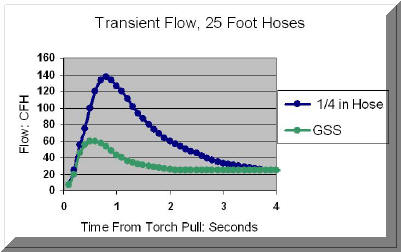
One visible result of the highly turbulent shielding gas flow at the weld start is excess weld spatter. In a number of applications we have measured 200 to 250 CFH surge flow at the weld start (systems with longer hoses and/or higher pressures.) This not only wastes gas but also causes inferior weld starts and internal if not external weld porosity. The accompanying graph shows the start surge flow with a standard 25 foot, 1/4 inch ID gas delivery hose and a 5/8 inch ID torch nozzle. Note, the blue line shows flow with a standard gas delivery hose with the peak flow at 140 CFH. It exceeds the 60 CFH maximum suggested flow rate for about 2 seconds. The graph in green was made with the same flow settings and same length Gas Saver System. Note the peak flow is about 60 CFH and quickly falls below 50 CFH. In addition to saving about 80% of the gas waste each time the torch switch is pulled, it still provides some extra gas at the weld start to purge the weld start area, etc. (SEE WHY EXTRA GAS AT THE WELD START IS IMPORTANT.) In addition the Gas Saver System does not alter the delivery hose pressure so Automatic Flow Compensation is maintained; a feature built into MIG gas delivery systems since the introduction of that welding process. (CLICK TO SEE WHAT AUTOMATIC FLOW COMPENSATION IS ABOUT ) One fabricator performing weld repairs found significant reduction in their weld start rejects when our Gas Saver System was used. CHECK OUT THE SPECIFICS.
|
|||||||||||||||||||||||||||
|
MIG shielding gas surge at the weld start is recognized as causing problems. Attempts have been made over the years to control the high flow start surge to reduce: 1. Turbulence that causes moisture laden air to be drawn into the shielding gas stream creating excess starting spatter and internal weld porosity. 2. Gas waste that accompanies the start gas surge (we have found this can be 50+% of overall gas usage!)
|
|||||||||||||||||||||||||||
|
Example of a welder that "Loves" our GSS Welders love the system since it: 1. Does not limit their options or interfere with their ability to adjust the steady state gas flow (If you want to limit flow adjustment see our patent pending Flow Rate Limiter.) 2. Improves weld starts by limiting peak surge flow rate to a level that does not create excess turbulence in the shielding gas stream. Sufficient extra gas is delivered at the weld start to purge the torch nozzle and start area of moisture laden air. 3. Maintains preset gas flow rate even when spatter builds in the torch nozzle or the torch gas hose becomes bent and twisted in the normal course of doing their job (this is what is referred to as �Automatic Flow Compensation" even though most welders and even some welding engineers never heard of the term!) 4. Is of rugged construction with a very heavy wall thickness, fiber reinforcement hose allowing it to be dragged on the shop flow without excess wear. It can be stepped on without restricting gas flow! 5. Has no knobs to adjust or moving parts to wear or require maintenance. |
|||||||||||||||||||||||||||
|
A review of some of the problems created by past attempts at solving weld start surge flow and gas waste follows:
|
|||||||||||||||||||||||||||
|
Use of Fixed Orifice to Limit Surge Flow
A
simple surge flow restriction orifice can be added to the wire feeder to
limit high gas surge at the weld start (we have measured
a. Properly sized this can work to reduce the undesirable effects of gas surge and improve weld start quality. However even if sized correctly when welding stops gas still builds in the delivery hose from gas supply to feeder. It is still wasted when welding starts! However rather than in a very short time with the very high gas surge it flows at the higher than steady state setting until the excess gas is gone. The waste still occurs it just takes somewhat longer and is less obvious! b. However we often find the orifice size is selected so the peak surge flow is set too low to fully purge the weld start area of moisture laden air. The high flow surge that caused start problems is eliminated but moisture laden air is still in the start area and causes similar weld start quality problems! Stauffer in his 1982 patent clearly defined this need, See what Stauffer said. Welders often can see this problem and counter by drilling out the orifice to �get more gas.� What they are doing is counterproductive but they are seeing the poor initial gas shielding and trying to solve the problem. See a production example of a similar problem solved with our GSS.
|
|||||||||||||||||||||||||||
|
Use of Low Pressure Devices to Reduce Surge
Note the Conventional Regulator Flowmeter maintained the preset 31 CFH without interaction by the welder. However with the Low Pressure Device flow varied from a high of 37 CFH to a low of 16 CFH! While this occurred the flow calibrated pressure gauge continued to read 31 CFH since it was really only reading pressure and gives no indication to the welder, welding foreman or welding engineer that flows change! Only measuring at the torch is the flow change detectable. This testimonial is from a welding engineer at an automotive OEM who removed and discarder 32 of these low pressure systems that mounted at their wire feeders after he discovered the inaccuracy�s of controlling flow with this approach.:
|
|||||||||||||||||||||||||||



 J.
F.
Lincoln�s Management System was threatened by US government policies in the
late 1930�s. He wrote a number of letters and articles about his concerns that
were published in local newspapers. Lincoln Electric workers were doing
well in a period where government intervention was making things worse! One
small section of our review contains quotes of his thoughts. The following
are some quotes abstracted from James Lincoln�s management books and one
written by Virginia Dawson in 1999 entitled �Lincoln-a history.,� All these
books are available from the James F. Lincoln Foundation Library at:
 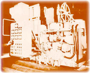 a welding equipment factory in West Germany. A large welding
fixture builder purchased our US made submerged arc equipment. I was
visiting to discuss a number of multi-electrode welding machines he was
selling to Russia. I asked if it bothered him to sell to the Russians since
it was obvious from his comments he had no love for them! He said, with a
laugh, �No,
because the central planners in Moscow always buy products the fabricating
plant does not need. In addition, by the time they transport the product to
a plant many of the parts are stolen!� (Picture left is the first 3-wire
submerged arc all AC power welding system that welded at 3000 amps making
large diameter natural gas and oil transmission pipe. We developed the
system in the late 1960's and 8 such systems were installed at this US Steel
Pipe Mill in Provo Utah, 11 at Armco Steel in Houston -and in a number of
other pipemills around the world -unfortunately, like
most USA UOE pipemills , those mentioned are no longer in existence!)
 accountable for abuses. However making
more complex laws in attempt to "manage" this function just leads to unintended
consequences. Just like NASCAR racing, make the rules apparently very
restrictive and racers still find ways to get around them-legally! It�s a
game! That is what is happening in Washington DC;
Lobbyists, Lawyers, Accountants and
Politicians become rich finding ways around complex unneeded laws!


 Daniel
Bernoulli


 about liquid gas tank
losses and questions such as; "Should pipelines be shut-off from the
liquid supply over a weekend?" Discussions with an engineer
from the leading US cryogenic tank producer provided some interesting
information. However since most of these tanks are rented to a
fabricator by the gas seller, the following is mostly useful in discussions with your supplier about the situation.
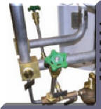 an "Economizer Circuit" (Photo Right) This is how it works: Cryogenic
tanks operate at
125 psi. They vent gas when the pressure exceeds 250 psi. The
pressure increases as heat inevitably enters the tank and evaporates some
liquid. The "Economizer
Circuit" delivers the higher pressure gas to the pipeline (F in Schematic
at top of page)
before sending liquid to the Evaporator (D in above schematic.) The
system utilizes this gas rather than vent it to the atmosphere. These
tanks can also retain Argon for a weekend without or with minimum venting to the
atmosphere!
This assumes the tank is properly sized (not excessively large) and is, on
average, half full.

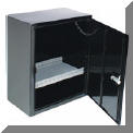 This
manufacturer of truck boxes selected a repetitive job of welding doors.
They put a full cylinder of shielding gas on one welding system with
the existing gas delivery hose. They welded 236
doors with that cylinder. They then put on a new full
cylinder and our
 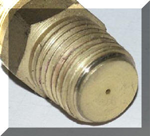 Did
you try an Orifice mounted at the wire feeder to set gas flow rate?
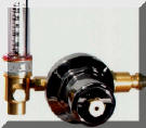 Have
you tried a "Low Pressure" Regulator/Flowmeter or Regulator/Flowgauge?
 Did
you try a surge flow reducing device with Both Problems - a Low Pressure
Device Mounted
at the Feeder?
  Our
Patented Gas Saver System (GSS
) has
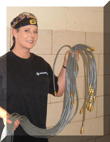
neither problem encountered with the above devices - or any other problems! (Picture shows Sue
holding 25 GSS's ready to be
installed at a welding school.)
  Reviewing
what two published reports say about the amount of MIG
shielding gas used by the average fabricator.
 Reviewing the above data it
becomes obvious that the high flow surge at the weld
start causes air to be pulled into the shielding gas stream and creates
inferior weld starts.
  The
patented Gas Saver System (
 surge peaks over 250 CFH in some applications which is much higher than the
level needed to avoid excess turbulence!) On the surface sounds like a
reasonable way to limit peak flow, but it creates other problems! The
restrictor can be implemented in two ways:
 �A
welding engineer at a major automotive sub supplier reports that after
purchasing and using 32 low pressure gas saving devices that mounted at
their wire feeders he had to discard all of them! He reported two problems: