


|
Why Simple Orifices, Flowmeters or Regulators, |
|
PROBLEM USING A FIXED ORIFICE TO SET SHIELDING GAS FLOW
An orifice can be placed at a wire feeder gas inlet to set the steady state shielding gas flow rate. Surge is reduced, however with this approach there is not enough extra gas at the weld start that creates a greater less obvious problem observed by a welder! This need was clearly defined in a 1982 patent by Stauffer, see Tech Details below. A FABRICATOR'S EXPERIANCE FOLLOWS
Seeing the excess starting spatter welders attempt
to compensate for the lack of sufficient extra start gas by increasing the steady state
flow rate. Although increased steady state flow can help, it's not as good as supplying extra gas quickly employing higher pressure and flow. A welder may set much higher steady state flow rates than needed. Gas waste from the
start
|
|
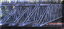
Production Example of Lack of Extra Start Gas
If sufficient shielding gas is not
provided at the start, welders may try to compensate by using higher overall
gas flow. A bar joist manufacturer was using flow control orifices
mounted at the wire feeders.
Tests were made to check weld performance and potential shielding gas savings using two cylinders of gas on two adjacent welders instead of from their pipeline gas supply. One welder was set with their standard flow control orifice system and a regulator providing a pressure that matched their pipeline pressure, 50 psi. The other with a regulator/flowmeter (also of a 50 psi design) using the same 15 foot length gas delivery hose GSS without their flow control orifice. Both steady state flows were set at their normal 45 CFH. Since welders stand side by side, it was easy to observe the weld start quality! Instantly the welder using the GSS noticed improved starting. After about an hour with observably better results with the GSS welder the welding engineer suggested we lower its shielding gas flow to 35 CFH! The same improved weld start quality was observed and the welder was "happy." In fact even though we lowered the steady-state flow to 35 CFH there was still about the same controlled amount of extra gas available at the start (that stored in the GSS hose when welding stopped.) The higher start gas flow rate established by the surge flow orifice in the GSS maintained the higher flow for a short time at the start. This higher start flow rate quickly flooded and purged the weld start area of moisture laden air. It was this air that was casing excess spatter and lack of start shielding on all their other welders! After about 4 hours of observation it was obvious the spatter at the weld start was less with the GSS. We also measured a reduced use of shielding gas of ~35%. After several months of testing to check this one system during windy days etc, this shop now has GSS's installed on all 50 welders! Bottom Line - - "Some extra gas flow at the start is very beneficial." In addition, after about a year of use their bulk gas supplier called to see if their business had turned down since they were using 30+% less gas- it had not! Note: Any flow control device installed right at the feeder, be it an orifice flow control, a flowmeter or a flow control regulator will have the same lack of sufficient initial shielding gas to purge the weld start area. |
|
STARTING PROBLEM WITH FLOWMETER PLACED AT WIRE FEEDER A review of the shielding gas flow rates in a shop with ~100 welders revealed the amount of excess gas flow each welder was using! DETAILS:
A shop with 100 MIG welders tried to
reduce gas waste
|

|

 Argon/CO2 shielding gas
is supplied in a pipeline through about 15 feet of gas delivery hose. The
flow control orifice established the flow at 45 CFH. However the welders
wanted higher flow rates with some even drilling out the orifice! The
welding engineer wanted to avoid wasting shielding gas. With this flow setting
arrangement where control is mounted at the feeder next to the gas solenoid
there is insufficient extra gas provided at the weld start. This lack of
extra gas prevents proper purging the weld start area of
moisture laden air.
Argon/CO2 shielding gas
is supplied in a pipeline through about 15 feet of gas delivery hose. The
flow control orifice established the flow at 45 CFH. However the welders
wanted higher flow rates with some even drilling out the orifice! The
welding engineer wanted to avoid wasting shielding gas. With this flow setting
arrangement where control is mounted at the feeder next to the gas solenoid
there is insufficient extra gas provided at the weld start. This lack of
extra gas prevents proper purging the weld start area of
moisture laden air. 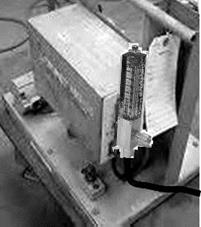 by installing flowmeters at the wire feeders. These were connected by a hose
to a 50 psi shielding gas pipeline. Most of the flowmeters were model L-32
(shown at right) read accurately when connected to a 50 psi gas line, so the flow readings
are direct.
by installing flowmeters at the wire feeders. These were connected by a hose
to a 50 psi shielding gas pipeline. Most of the flowmeters were model L-32
(shown at right) read accurately when connected to a 50 psi gas line, so the flow readings
are direct. 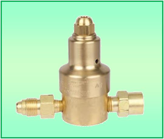 "automatic flow compensation."
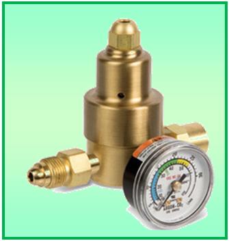 any device mounted at the gas inlet on a wire feeder - LACK OF NEEDED PURGE GAS AT WELD STARTS.
  The
The 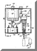 The need for some extra gas at the weld start was clearly defined in a 1982 patent by Stauffer. As he outlined, a sufficient quality of shielding gas must be quickly delivered at the start of a weld to purge moisture laden air from the weld start area and MIG gun nozzle. The figure right is from his patent. He added a rather large reservoir (item 112 in the figure) in his device because it operated at lower pressure. Although the lower pressure feature caused flow variations I have a specific experience in Pulsed MIG welding where weld starts were significantly improved over the "gas blast" caused by conventional flow controls.