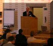
mig controlwasteTOMindexlogo 


After presenting  a technical talk  on "Managing Shielding Gas," at a conference in Denmark, an interesting question was asked during the discussion?

Are their more elaborate systems available that control and save shielding gas other than the Gas Saver System described?

The question is of interest since it implies that our patented  Gas Saver System is too simple and more elaborate ways to solve this problem must exist!

In fact, more elaborate systems that work are covered by our  recent US Patents #'s 7,015,412 and 7,019,428!  SEE BELOW

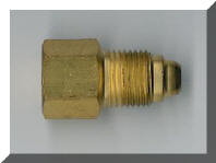
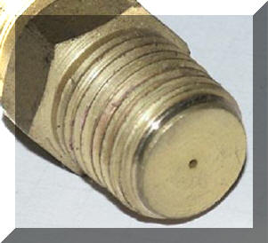
The following are some devices that have been tried but create more problems then they attempt to solve and are often rejected:

LOW PRESSURE SYSTEMS

Using low pressure delivery systems reduces gas surge and waste but eliminates the "automatic flow compensation" built into gas delivery systems since the introduction of MIG welding in the 1950's!  This creates significant flow variations while welding.

See Problems Low Pressure Systems Create

CONTROL OF FLOW AT THE FEEDER

Orifices, Flowmeters or Needle Valve controls placed at the feeder inlet reduce surge but do not provide sufficient extra gas needed at the weld start to purge the weld start area and torch nozzle of moisture laden air.  This was clearly understood by Stauffer in a 1982 patent where he stated;  "... air leaks back into the torch and lines when welding is stopped.  The air must be quickly purged and replaced with inert gas to produce high quality welds. Also, it is critical to displace the air at the weld zone of the work piece upon initiating the weld.

Welders often sense this lack of needed extra start gas and drill out the orifice in attempt to compensate!

See More Details About This Feature

COMBINED LOW PRESSURE DEVICE MOUNTED AT FEEDER

Low pressure devices that mount at the feeder create both of the problems mentioned above!  We have found welders can observe the lack of initial extra gas at the start and increase the overall flow in attempt to compensate!

See A Welding Engineers Production Experience Where 32 of These Devices Were Removed and Discarded!

SURGE CONTROL ORIFICE  PLACED AT THE FEEDER

Perhaps the most deceptive result  is created by an orifice placed at the wire feeder but sized just to control surge flow while steady state flow control remains at the gas source. 

This gives the impression that shielding gas waste is eliminated since the peak surge flow is reduced.  In fact you can hear the reduction in peak flow, and weld starts are improved.  However the pressure in the delivery hose still increases to that of the regulator or pipeline when welding stops!  When welding, the pressure reduces to the low level that is needed to flow the desired gas flow rate.  Where does the excess stored gas go?  It's wasted - - it just takes longer for the excess stored gas waste to exit the torch! 

When employing this approach, the surge orifice size must  be selected  to quickly provide sufficient extra gas to fully purge air in the weld start zone (we find some are set too small.)  A properly sized  surge control orifice may save 5 to 10% shielding gas due to a small pressure drop at typical flow rates.   But that is not anywhere near the 80% saved using a GSS with its 75% reduced stored gas volume.   The patented GSS  quickly  provides enough extra gas at a flow rate which is substantially higher than the steady state flow but at a level that voids pulling in the surrounding moisture laden air.  Note with no control added shielding gas is not only wasted but peak surge flow can exceed 150 to 200 CFH which draws in moisture laden air into the gas steam resulting in poorer starts and possibly internal weld porosity.

See Overview of GSS Features

Still Interested In More Elaborates Shielding Gas Control Systems? 

The 28 claims coved by our 2006 US patents #'s 7,015,412 and 7,019,428  define a number of viable options to control flow.  However these systems are more complex than the simple GSS and some require the use of multiple devices.  They are useful in situations such as when the gas delivery hose from flow control to the wire feeder gas solenoid are greater than 75 to 100 feet. 

Email with Your Requirements